Table of Contents
The base class ChSteering imposes that any derived steering mechanism class (a steering mechanism template) provide a steering link body to which a steerable suspension can be sonnected (usually through the suspension's tierods).
A derived steering mechanism type defines the bodies, joints, force elements, and topology of a particular type of steering mechanism. All locations are assumed to be provided with respect to a mechanism reference frame (a derived steering mechanism type is free to pick the location and orientation of this frame).
A steering mechanism assembly is attached to a vehicle's chassis by specifying the location and orientation of the mechanism assembly reference frame with respect to the chassis reference frame (see the definition of the ISO reference frame).
A wheeled vehicle may have multiple steering mechanisms, each associated with a different steerable vehicle axle. Similalry, a single steering mechanism may be connected to multiple steerable vehicle axles.
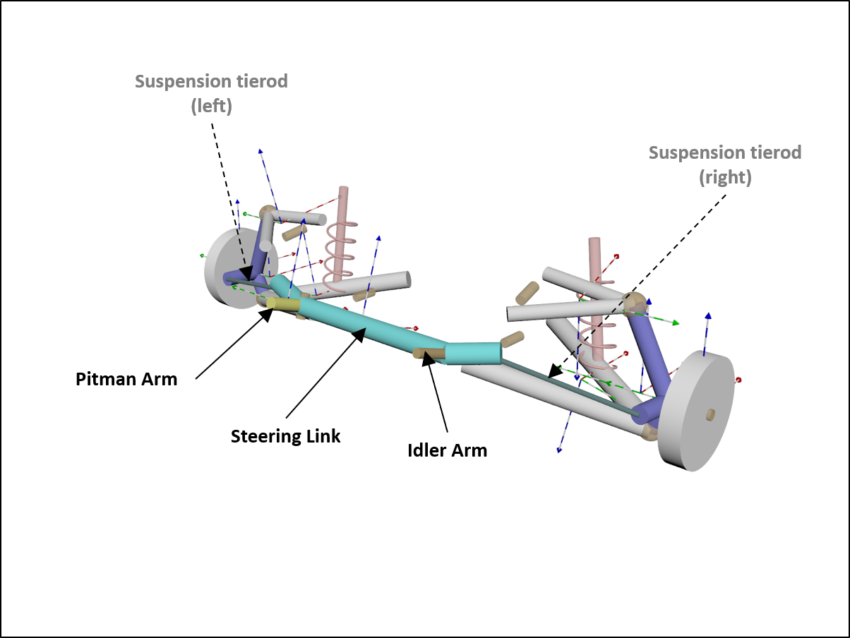
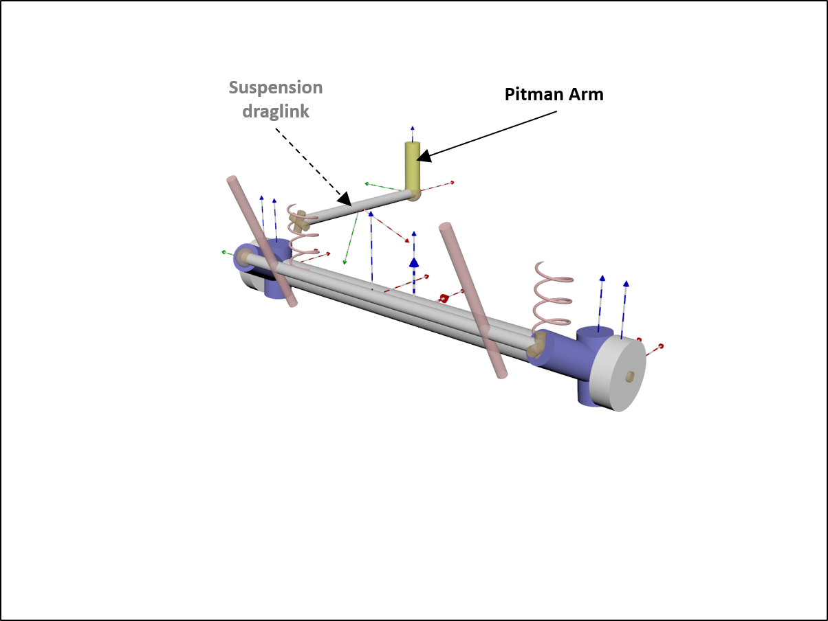
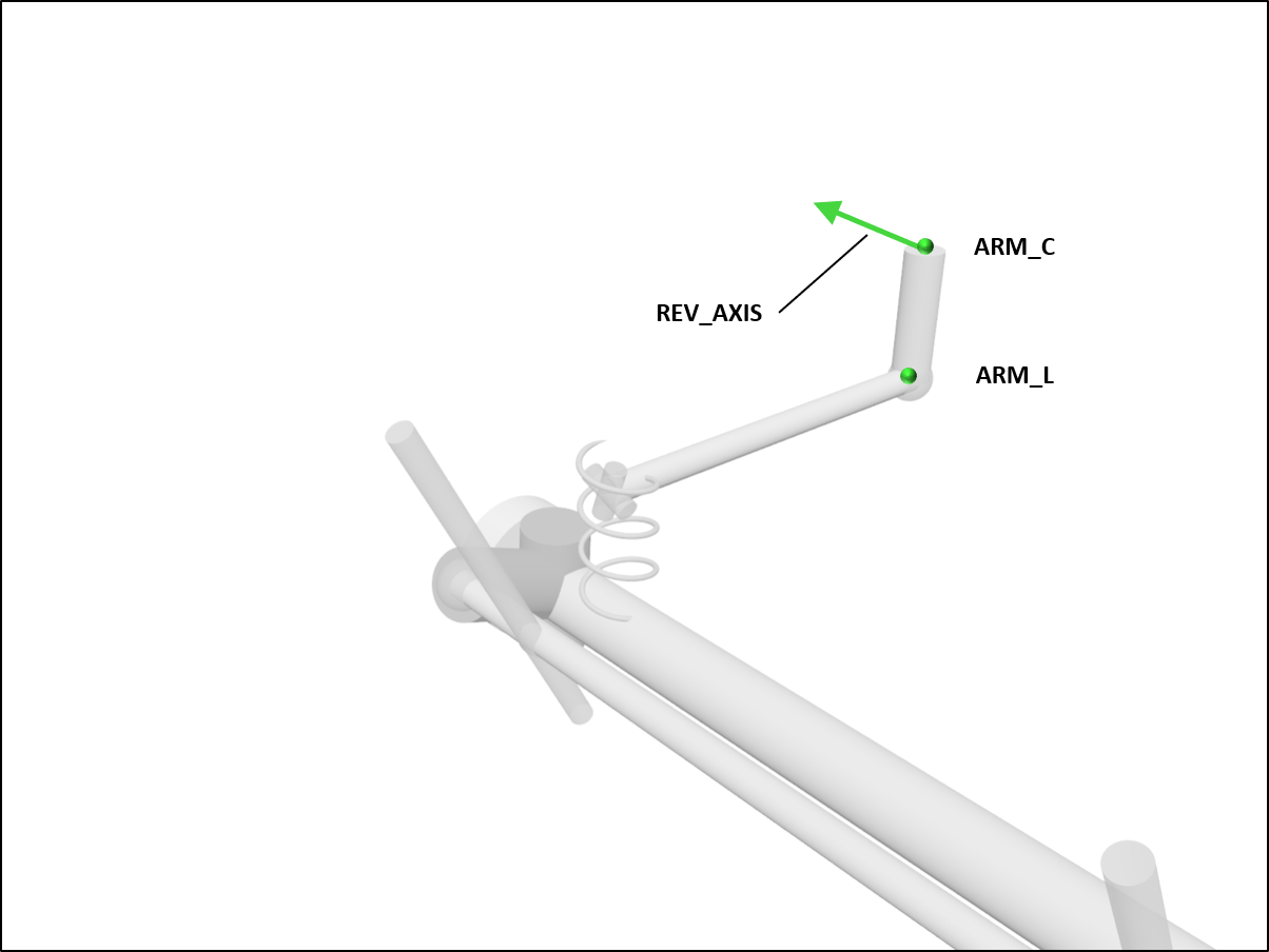
Pitman arm
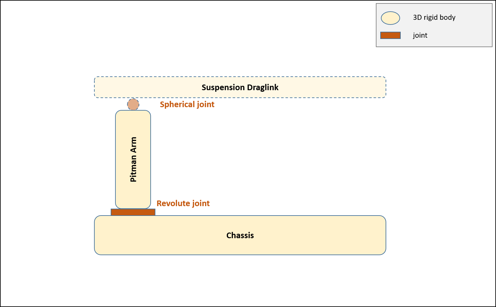
This steering mechanism is a four-bar linkage with the steering link body connected to the chassis via the Pitman arm and an idler arm. The Pitman arm body is connected through an universal joint to the steering link and a revolute joint to the chassis. The driver steering input is used to control the angle of the revolute joint. In the Chrono::Vehicle Pitman arm template, the idler arm is modeled using a composite revolute-spherical joint.
See ChPitmanArm and PitmanArm.
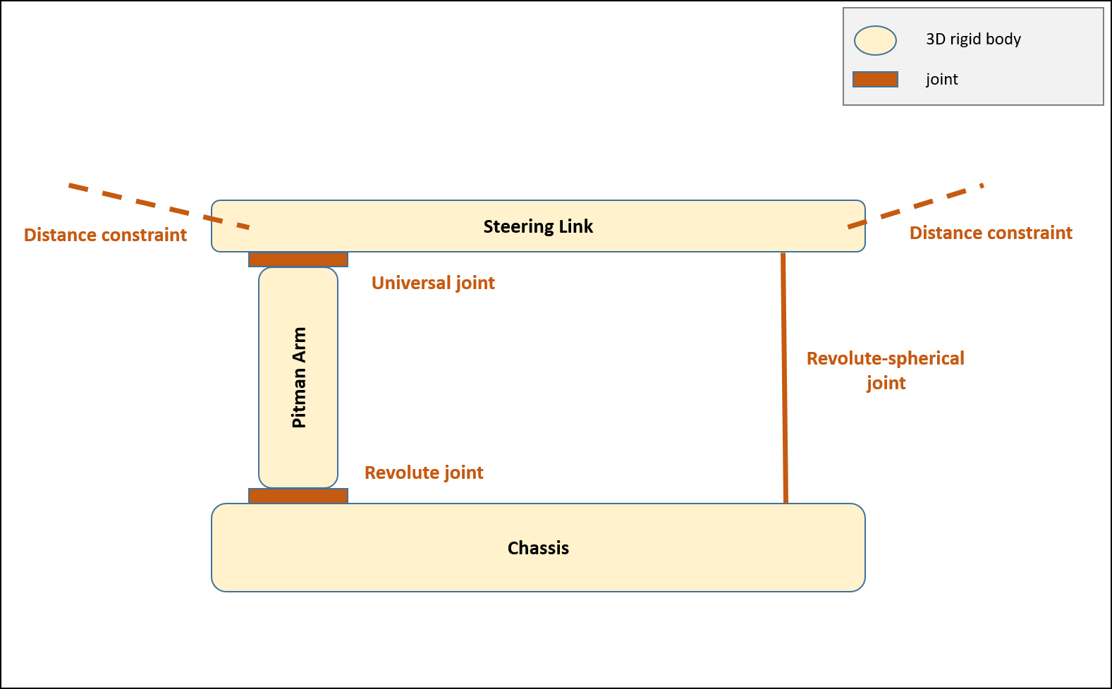
The topology of this steering mechanism template is:
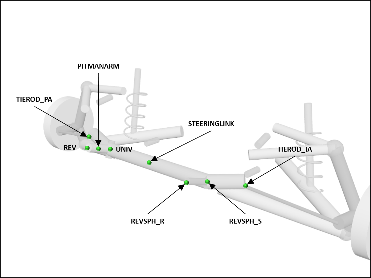
The hardpoints are:
A sample JSON file with the specification of a PitmanArm steering mechanism is:
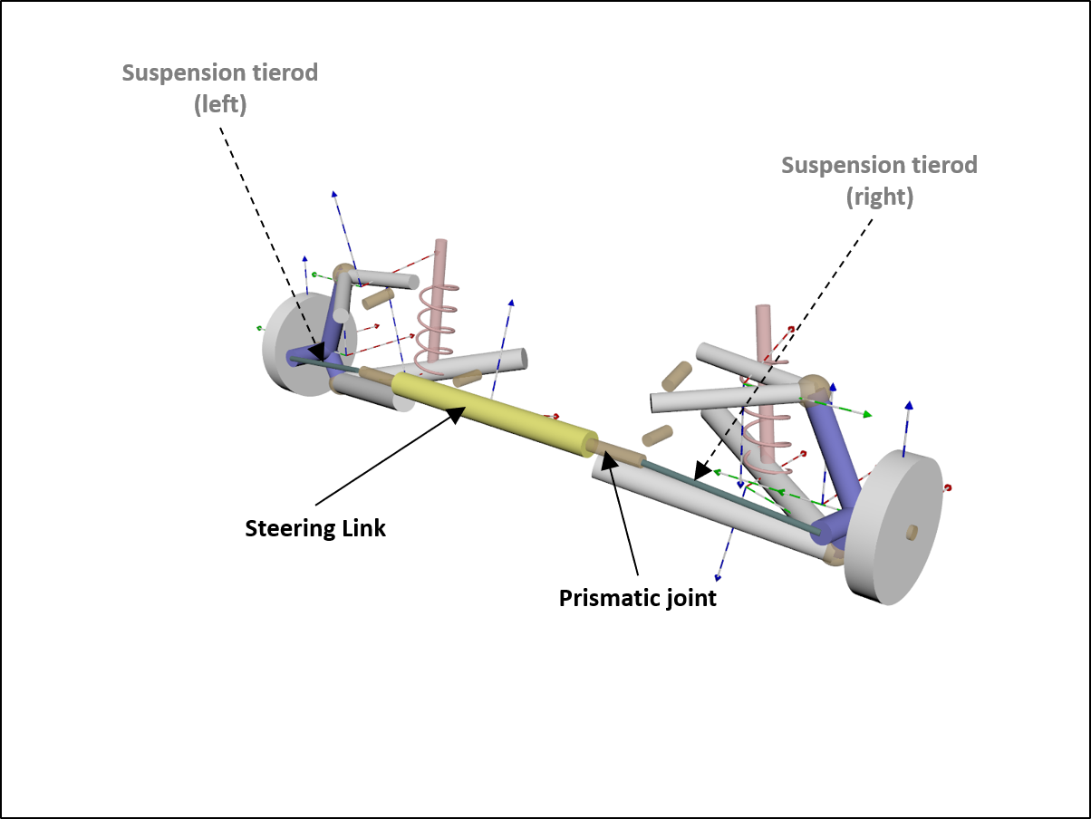
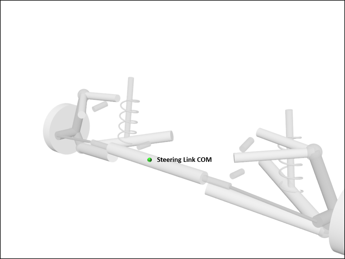
Rack-pinion
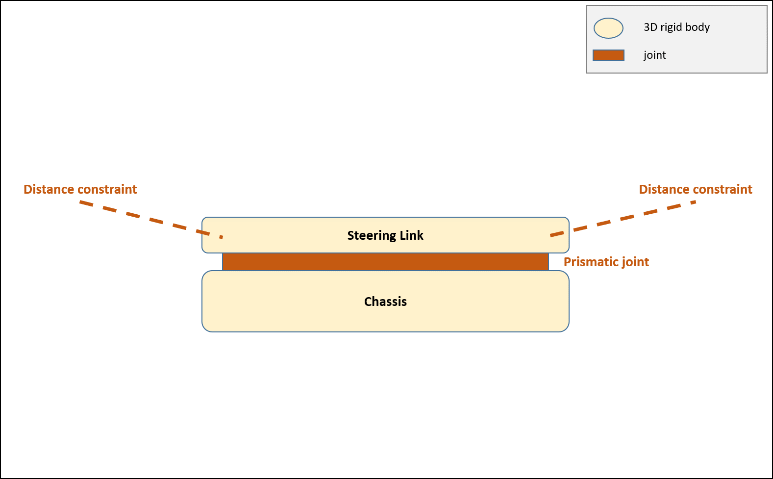
The Chrono::Vehicle rack-pinion steering template is a kinematic model of a rack and pinion steering mechanism. The steering link body is connected through a prismatic joint to the chassis. The rack displacement is calculated as:
\[ d = r (\alpha_{max} s) \]
where \( r \) is the pinion radius, \( \alpha_{max} \) is the maximum pinion angle, and \( s \in [-1,1] \) is the driver steering input. This displacement is used to control the translation of the steering link.
See ChRackPinion and RackPinion.
The topology of this steering mechanism template is:
The hardpoints are:
A sample JSON file with the specification of a RackPinion steering mechanism is:
Rotary arm
The rotary arm steering is a simple lever arm that rotates around an axis. It works with solid bellcrank axles and solid toebar axles. It is often used as steering system for trucks, farm tractors and combine harvesters.
See ChRotaryArm and RotaryArm.
The topology of this steering mechanism template is:
The hardpoints are:
A sample JSON file with the specification of a RotaryArm steering mechanism is: