The Chrono::Sensor module provides support for simulating RGB cameras, lidar, radar, GPS, and accelerometer, gyroscope, and magnetometer within a Chrono simulation. Sensors are objects that are attached to Chrono Bodies(ChBody). Chrono::Sensor is currently compatible with the core rigid body simulation in Chrono including Chrono::Vehicle.
Detailed overview of Chrono::Sensor.
How the sensor system is setup (more examples can be found in the sensor demos)
Chrono::Sensor design considerations
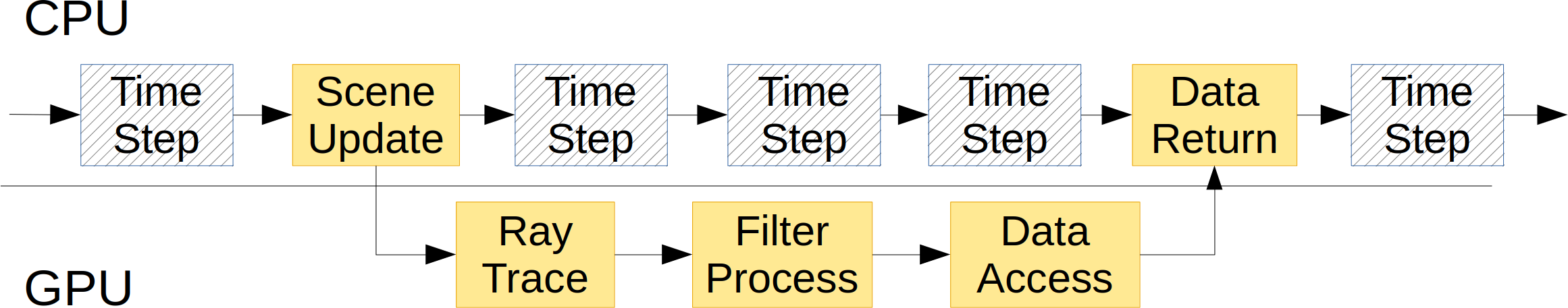
Since dynamic chrono simulations typically have a higher update frequency than sensors (dynamics: order 1kHz; sensors: 10-100Hz), the sensor framework uses a separate thread to manage the data curation.
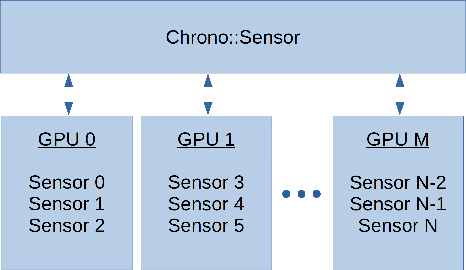
Chrono::Sensor can leverage multiple render threads each managing a separate GPU for simulating a group of sensors. This is particularly useful for scenarios with multiple agents and numerous sensors that operate at various update frequencies.
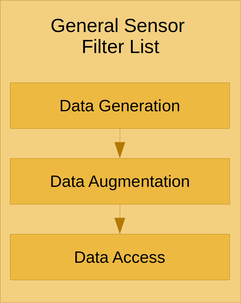
Each sensor has a filter graph which users can extend to customize the computation pipeline for modeling specific sensor attributes or configuring specific data formats.
Loading sensor models from JSON Files
Reference Frames and Relative Attachment Positions
Each Chrono sensor defaults to Z-up, X-forwad, and Y-left to match a vehicle ISO reference frame. For an RGB camera, this means that the z-axis points vertically in the image plane, the y-axis points left in the image plane, and the x-axis points into the image plane. For lidar, the x-axis point along rays with zero vertical angle and zero horizontal angle