Table of Contents
- Double wishbone
- Double wishbone (simplified)
- MacPherson strut
- Multi-link
- Semi-trailing arm
- Solid axle
- Solid three-link axle
- Solid three-link axle with bellcrank
- Leaf-spring solid axle
- Leaf-spring solid axle with toebar
- SAE Leaf-spring solid axle
- SAE Leaf-spring solid axle with toebar
- Three-link Independent Rear Suspension
- Rigid suspension
- Rigid pinned-axle
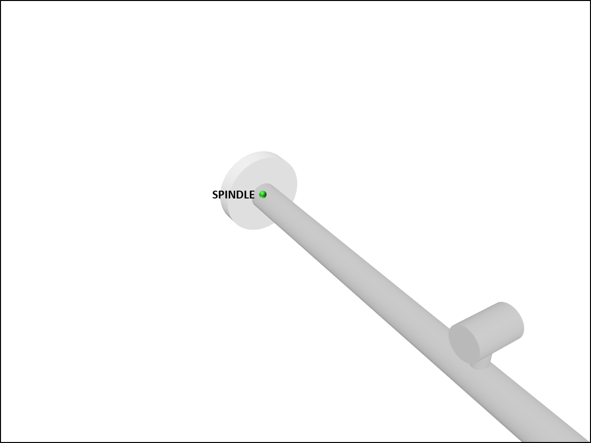
A suspension subsystem is a model of one axle of a wheeld vehicle. The base class ChSuspension imposes that any derived suspension class (a suspension template) provide two wheel spindles (left and right) each connected through a revolute joint to some part of that type of suspension, and two spindle axles (elements of ChShaft type) which may be connected to a vehicle driveline if that axle is driven.
A derived suspension type defines the bodies, joints, force elements, and topology of a particular type of suspension. All locations are assumed to be provided with respect to a suspension reference frame (a derived suspension type is free to pick the location of this frame but not its orientation, which is assumed to be parallel to the chassis ISO reference frame).
A suspension assembly is attached to a vehicle's chassis by specifying the location of the suspension assembly reference frame with respect to the chassis reference frame (see the definition of the ISO reference frame).
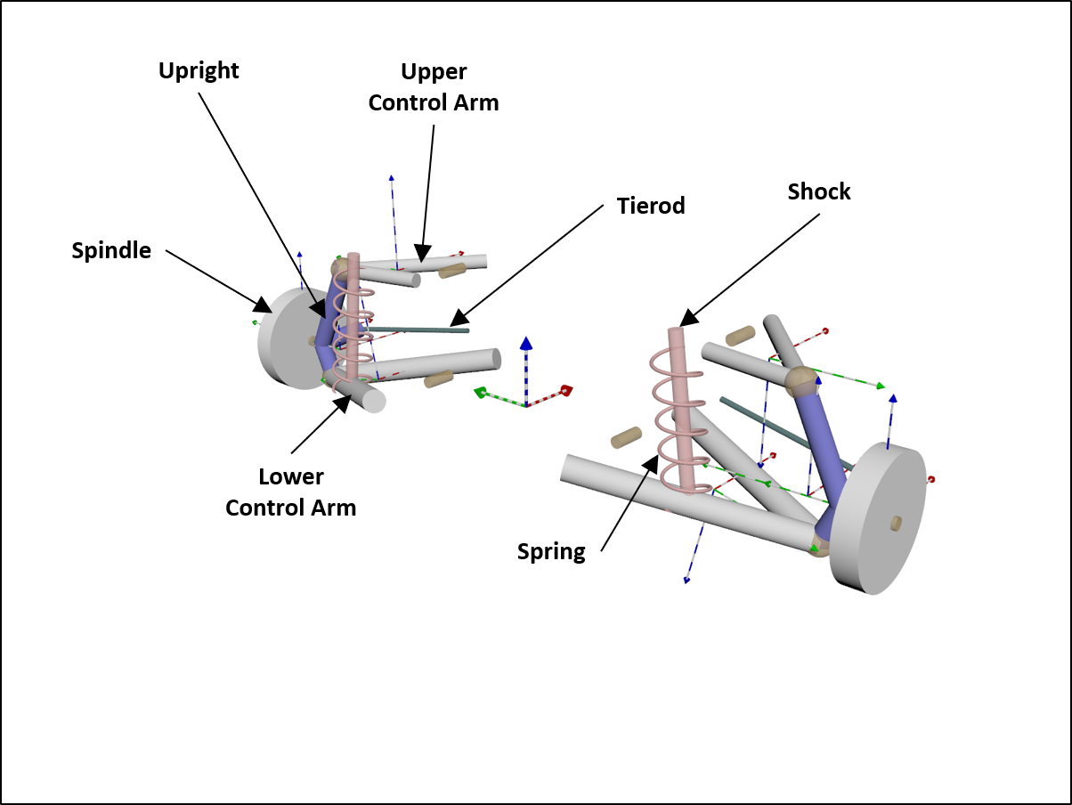
Double wishbone
Independent steerable suspension using two wishbone control arms (also know as A-arms) to connect the knuckle and chassis. Used as both front and rear suspension on the HMMWV vehicle model.
See ChDoubleWishbone and DoubleWishbone.
The topology of this suspension template is:
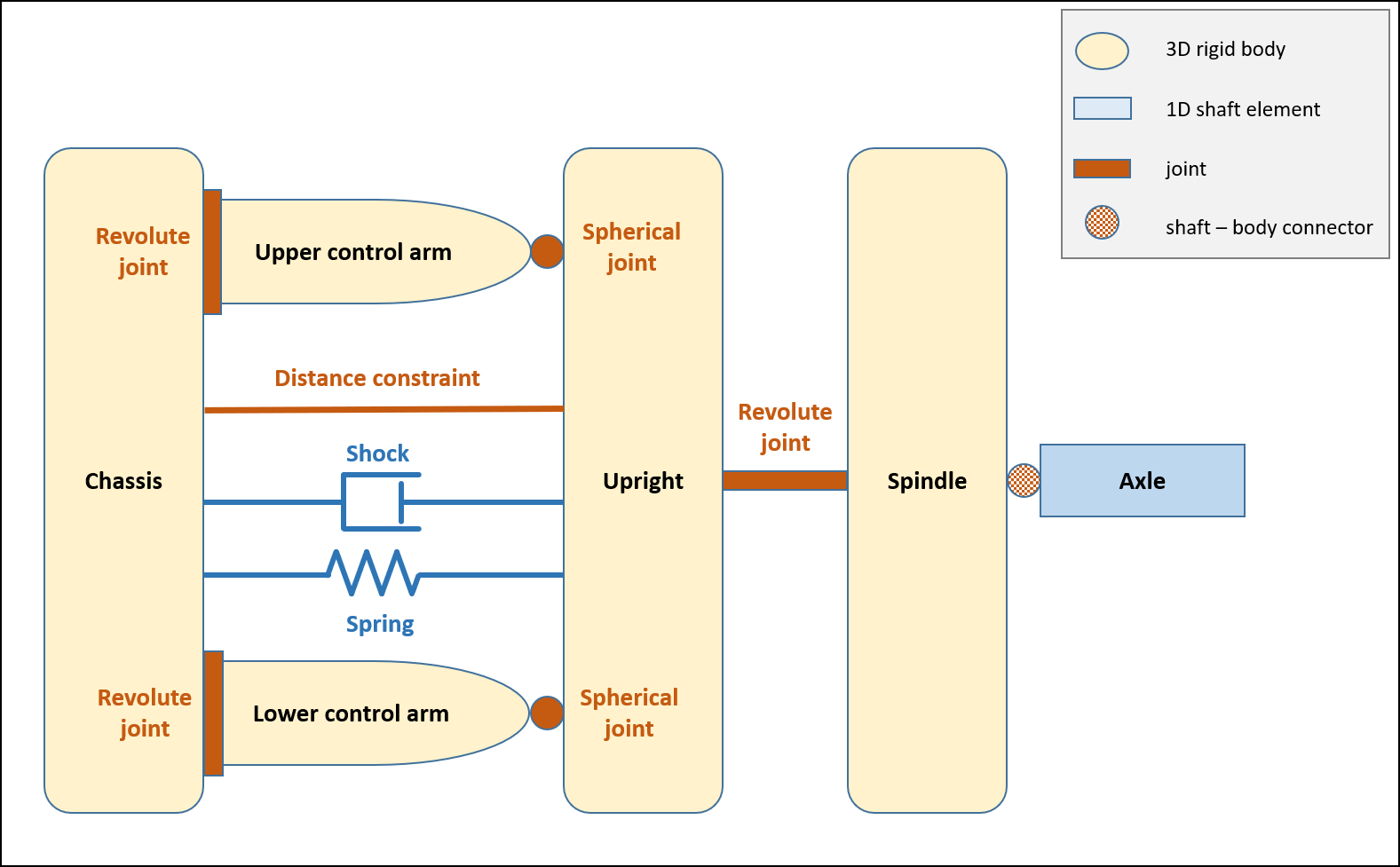
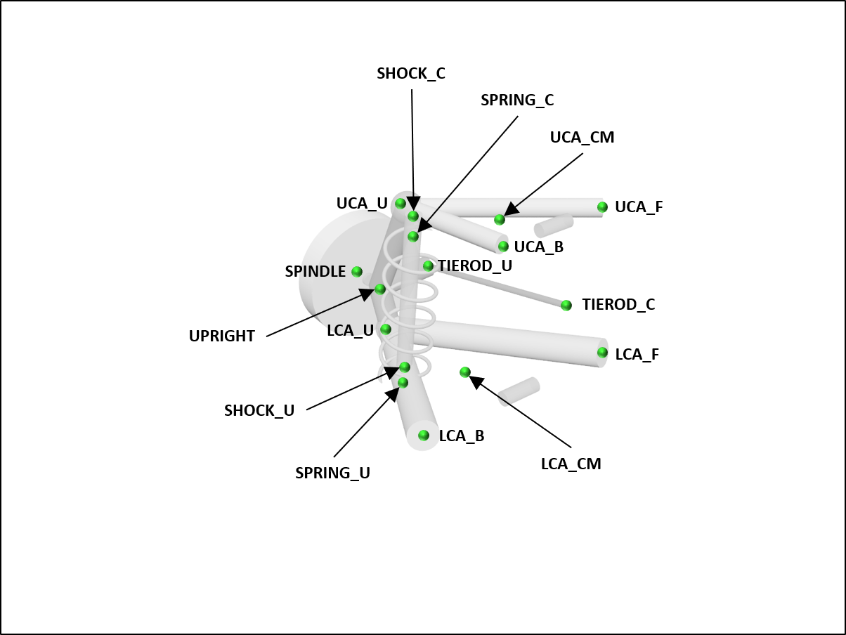
The hardpoints (defined for the left side only and mirrored to construct the right side) are:
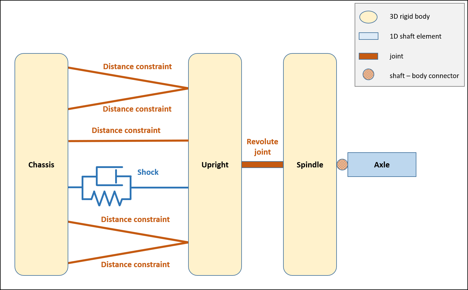
Double wishbone (simplified)
This simplified double-wishbone suspension template models the lower and upper control arms using two distance constraints for each. This suspension type is suitable when the mass and inertia of the control arms are small relative to the other bodies in the system and can therefore be neglected.
See ChDoubleWishboneReduced and DoubleWishboneReduced.

The topology of this suspension template is:
The hardpoints (defined for the left side only and mirrored to construct the right side) are:
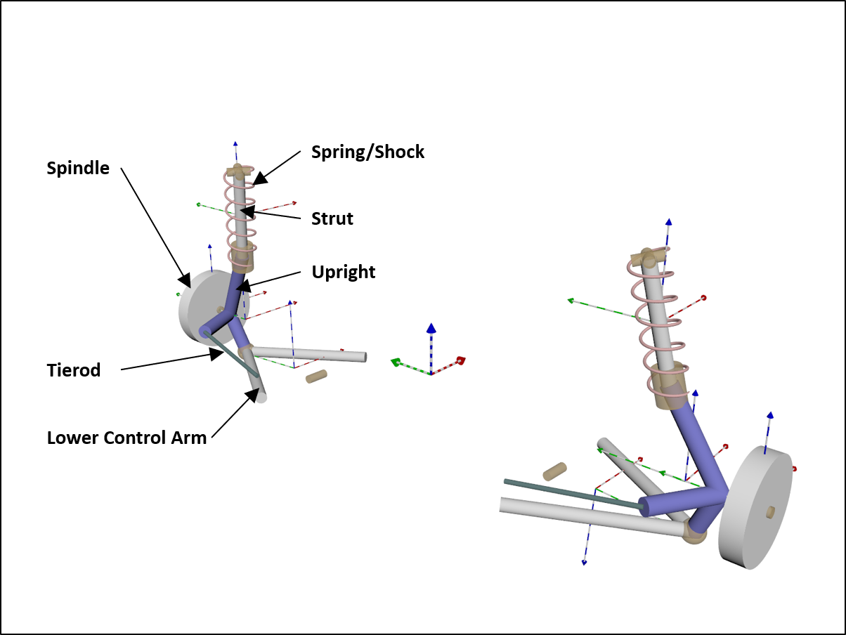
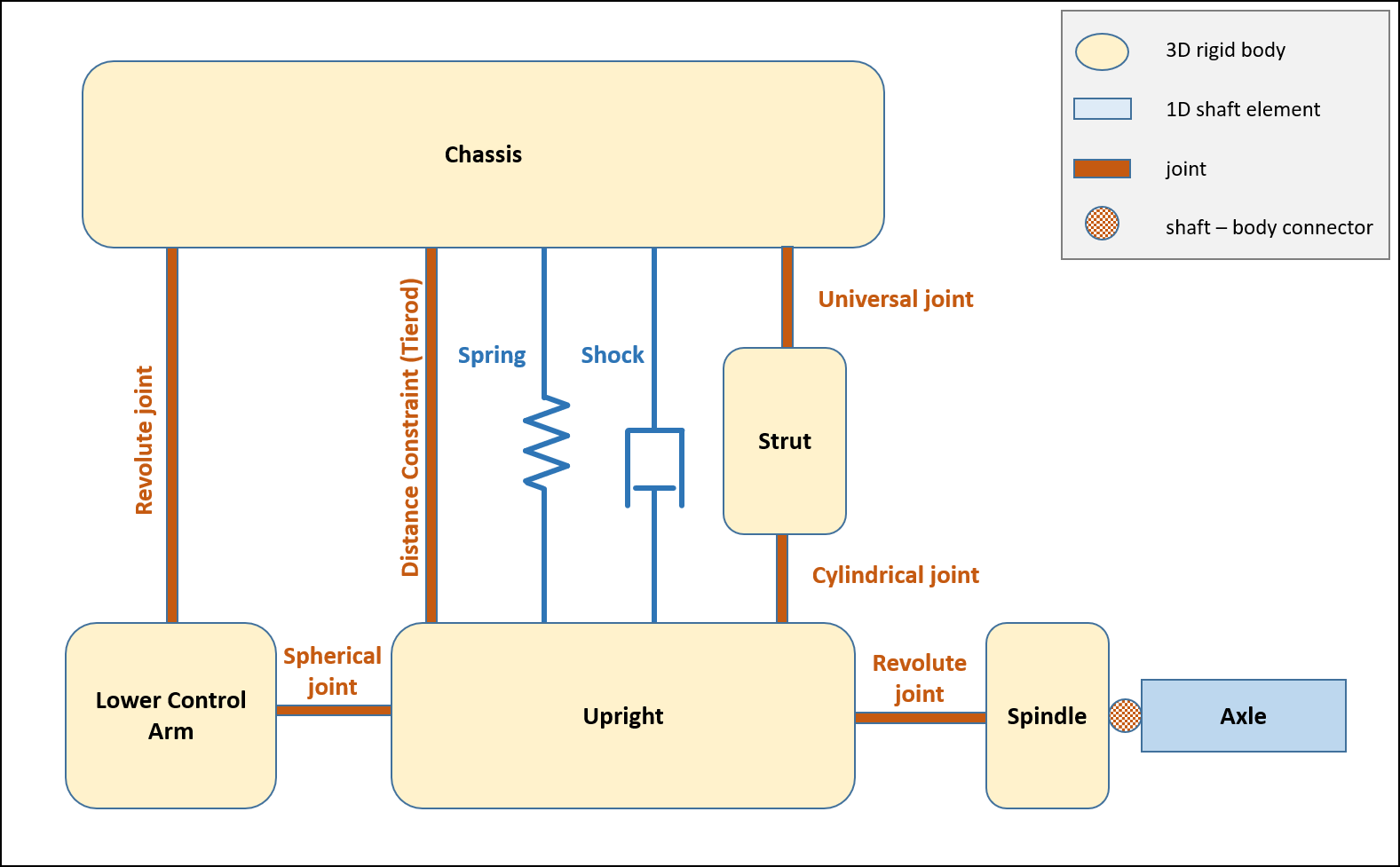
MacPherson strut
Steerable independent suspension system which is preferred for small to mid-sized passenger cars with front wheel drive and traverse mounted engine/gearbox.
See ChMacPhersonStrut and MacPhersonStrut.
The topology of this suspension template is:
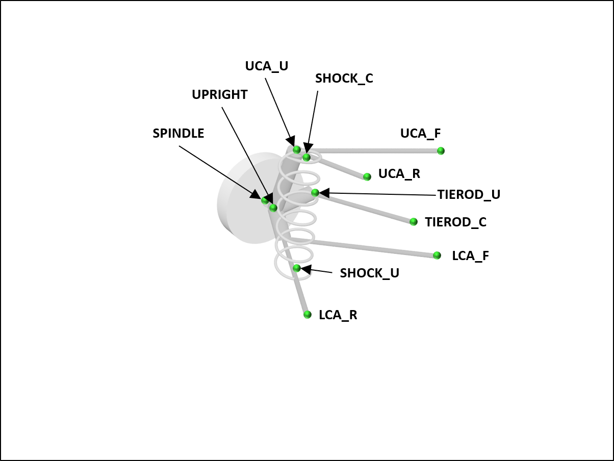
The hardpoints (defined for the left side only and mirrored to construct the right side) are:
Multi-link
This suspension system is similar to a double wishbone axle. The trailing arm can bear high longitudinal forces.
See ChMultiLink and MultiLink.
The topology of this suspension template is:
The hardpoints (defined for the left side only and mirrored to construct the right side) are:
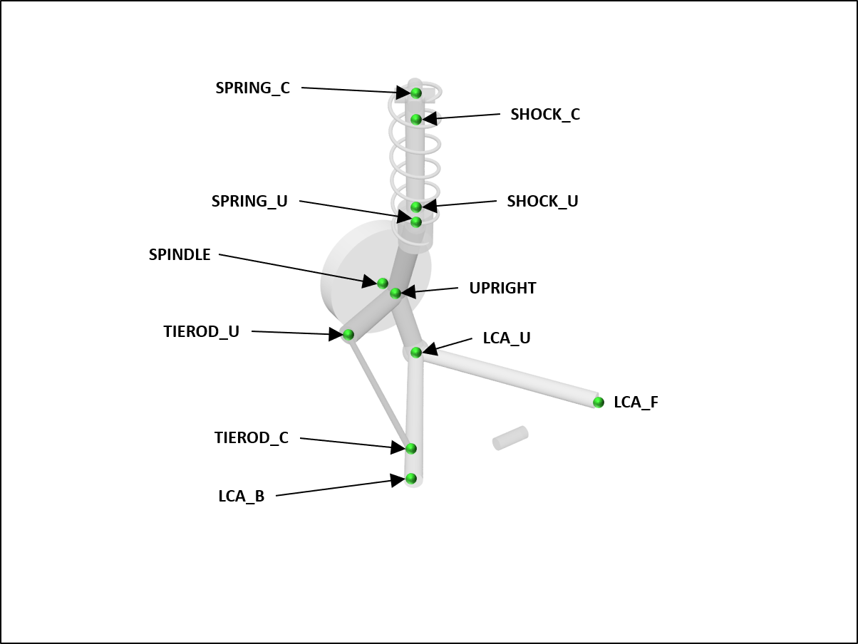
Semi-trailing arm
Simple independent axle system used in smaller passenger cars as rear suspension.
See ChSemiTrailingArm and SemiTrailingArm.
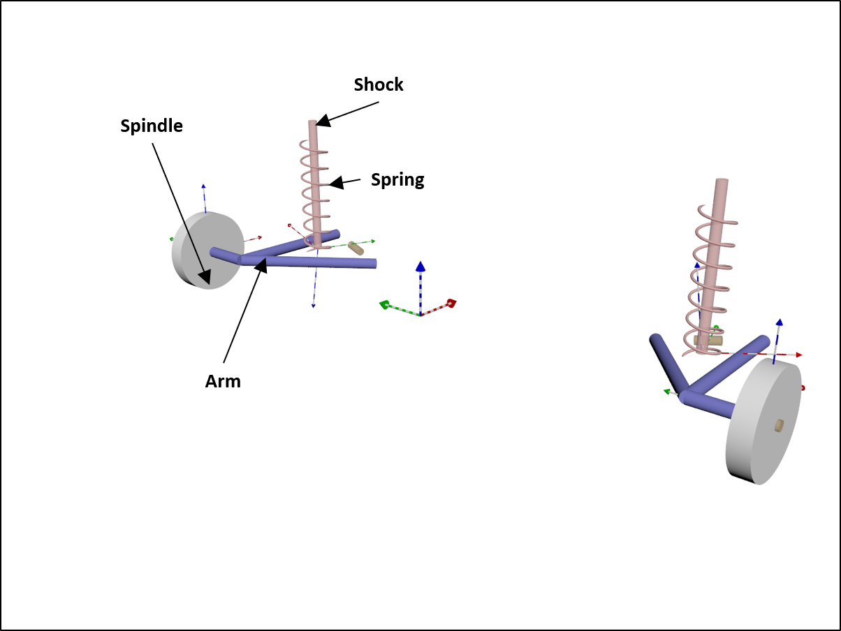
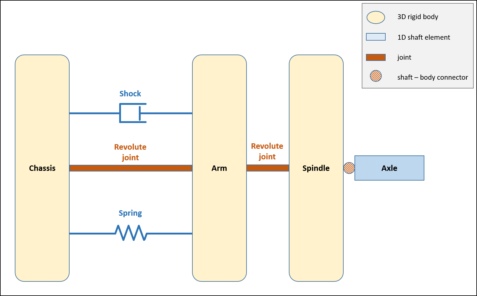
The topology of this suspension template is:
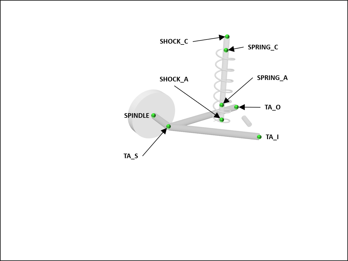
The hardpoints (defined for the left side only and mirrored to construct the right side) are:
Solid axle
A solid axle system guided by four links. It normally uses coilsprings or airsprings and could be found in older passenger cars.
See ChSolidAxle and SolidAxle.
The topology of this suspension template is:
The hardpoints (defined for the left side only and mirrored to construct the right side) are:
Solid three-link axle
Used as rear suspensions on the MAN 5t, MAN 7t, and MAN 10t truck models. This suspension allows very high wheel travel, which could not be realized with leafsprings. It is also in on-road trucks with airsprings. Airsprings and coilsprings need a suspension guided by links.
See ChSolidThreeLinkAxle and SolidThreeLinkAxle.
The topology of this suspension template is:
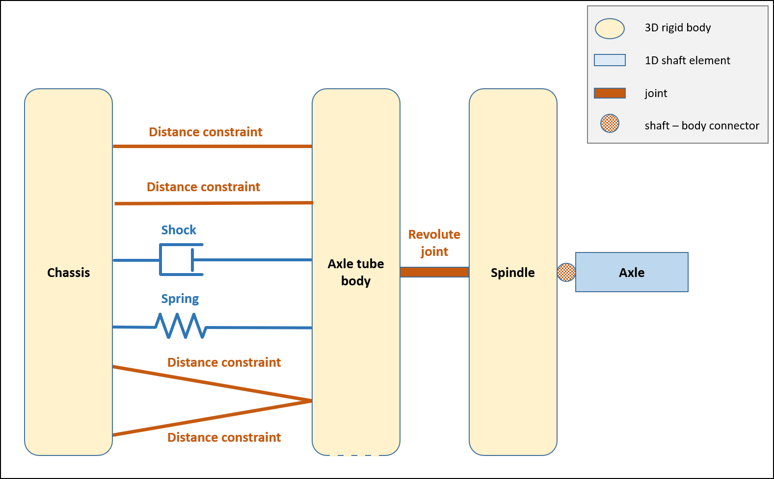
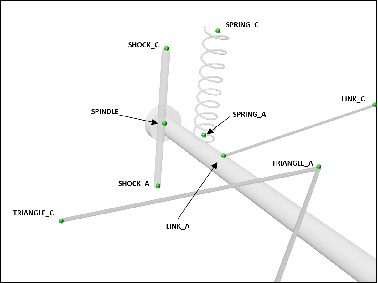
The hardpoints (defined for the left side only and mirrored to construct the right side) are:
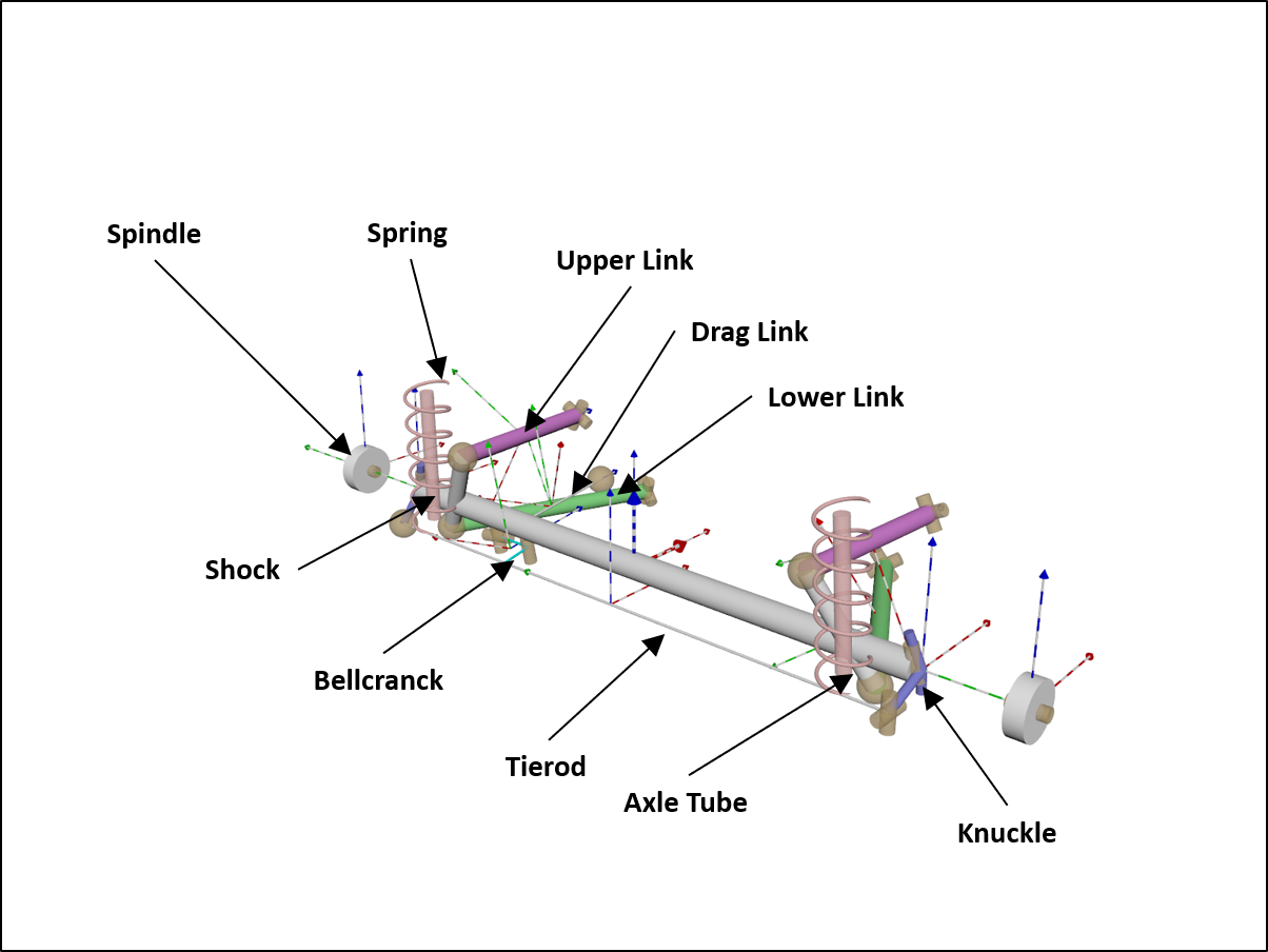
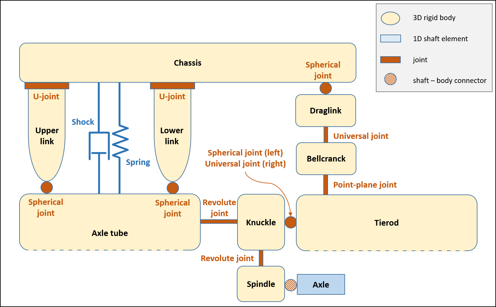
Solid three-link axle with bellcrank
Used as front suspensions on the MAN 5t, MAN 7t, and MAN 10t truck models.
See ChSolidBellcrankThreeLinkAxle and SolidBellcrankThreeLinkAxle.
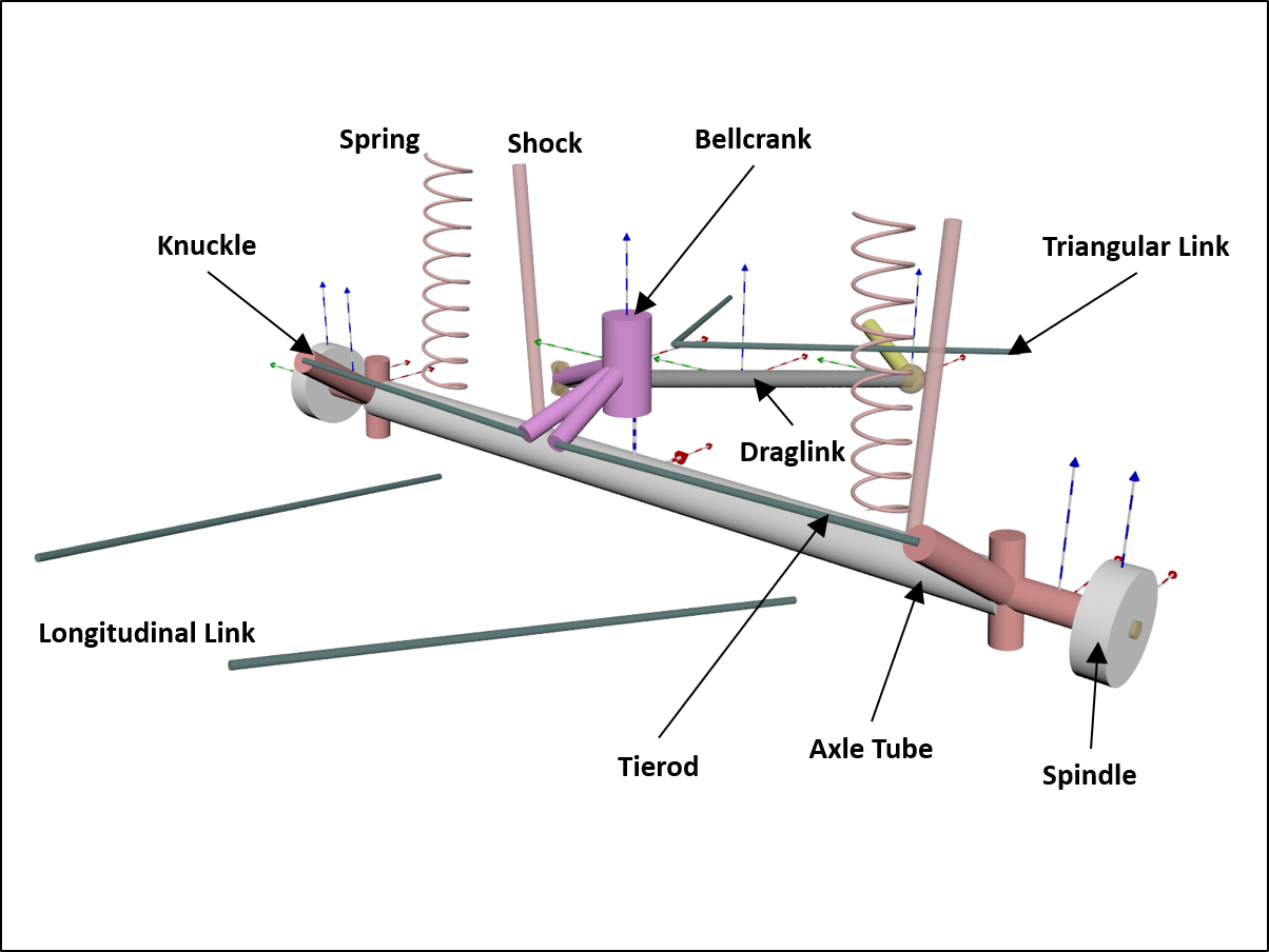
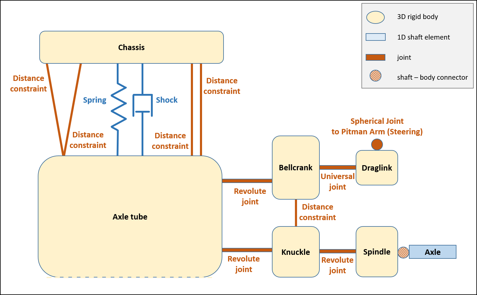
The topology of this suspension template is:
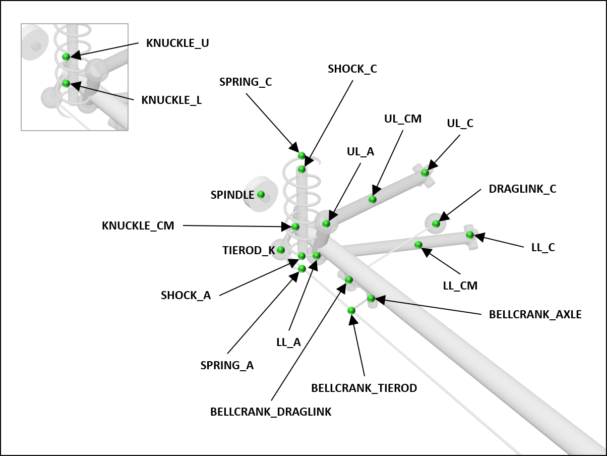
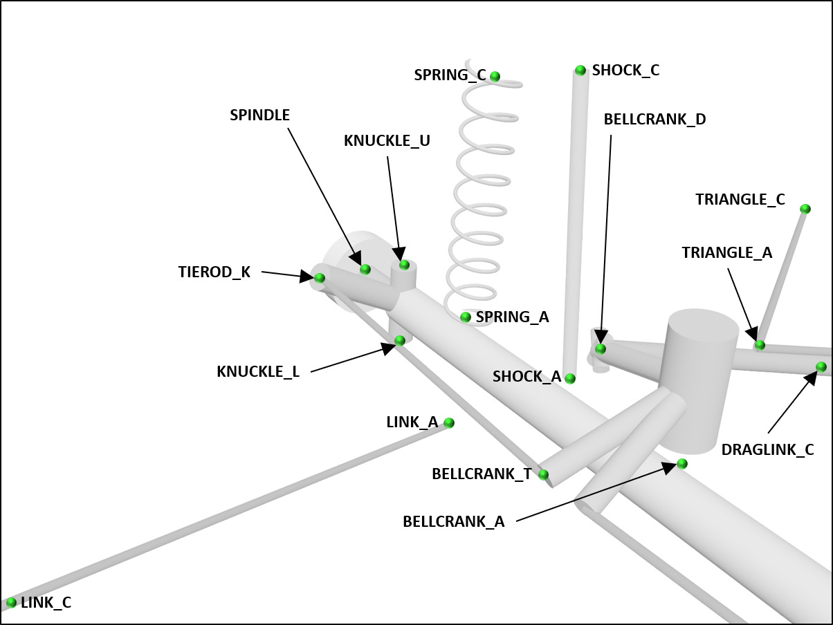
The hardpoints (defined for the left side only and mirrored to construct the right side) are:
Leaf-spring solid axle
Used as rear suspension on the UAZ vehicle models. Leafspring axles have complex guiding behavior. This is a work-a-like solution, where the guiding effect of the leafsprings is simulated by a special joint in the center of the axle tube. The suspension effect is modeled by coil springs. The rolling behavior is close to a real leafspring axle.
See ChLeafspringAxle and LeafspringAxle.
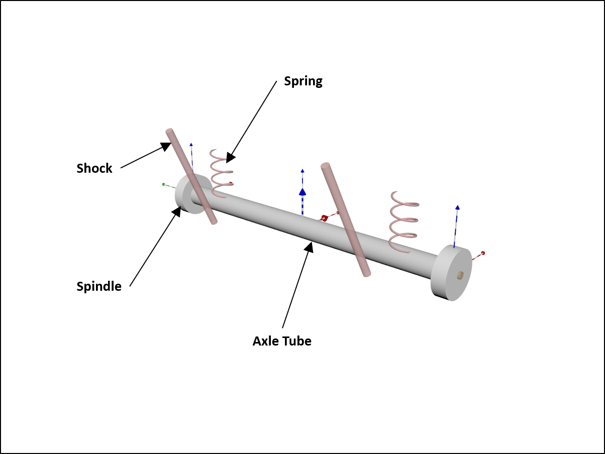
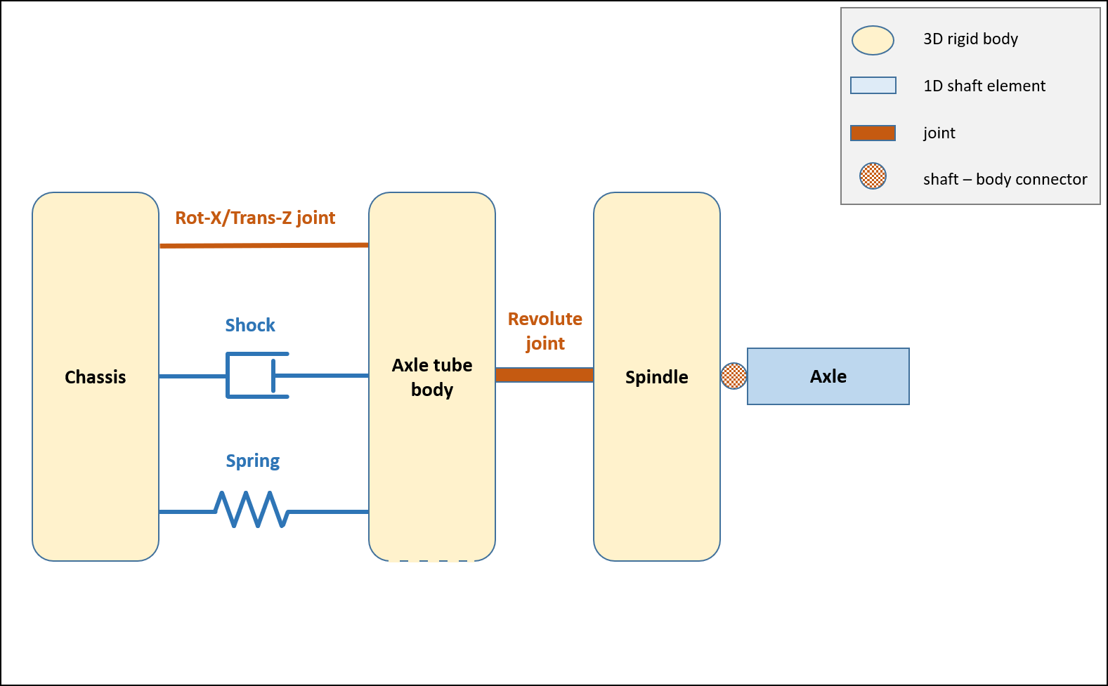
The topology of this suspension template is:
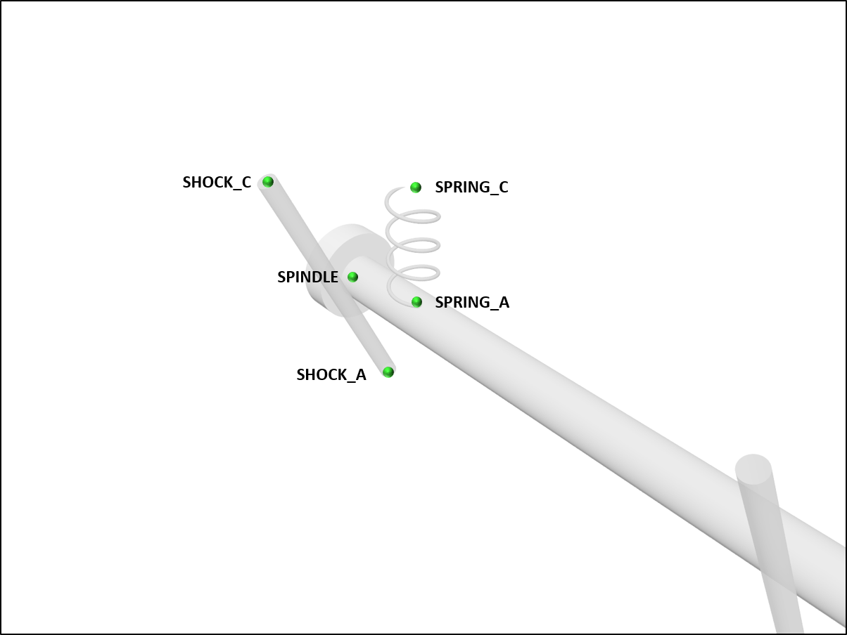
The hardpoints (defined for the left side only and mirrored to construct the right side) are:
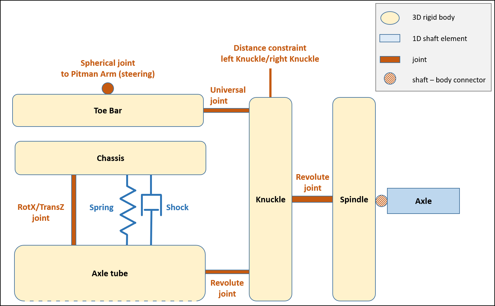
Leaf-spring solid axle with toebar
Used as front suspension on the UAZ vehicle models.
See ChToeBarLeafspringAxle and ToeBarLeafspringAxle.
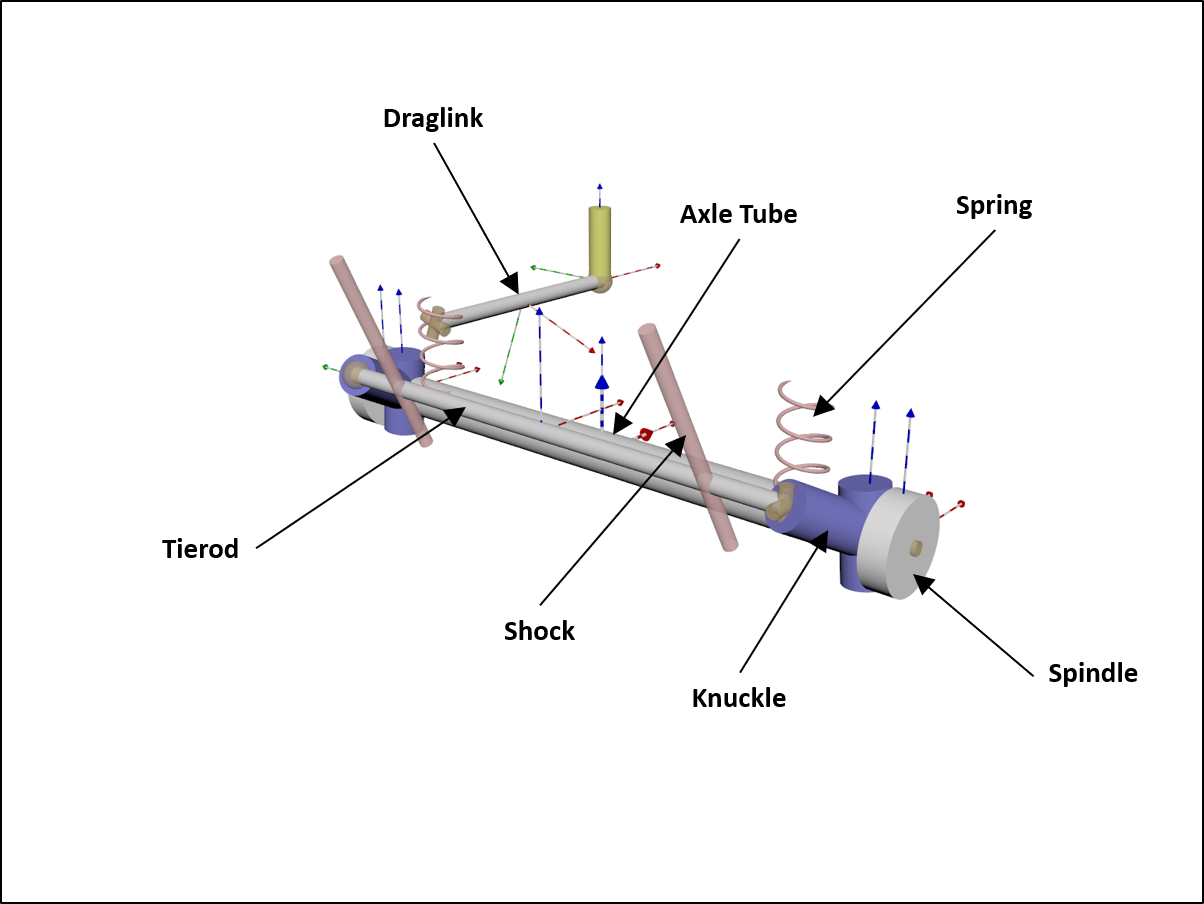
The topology of this suspension template is:
The hardpoints (defined for the left side only and mirrored to construct the right side) are:
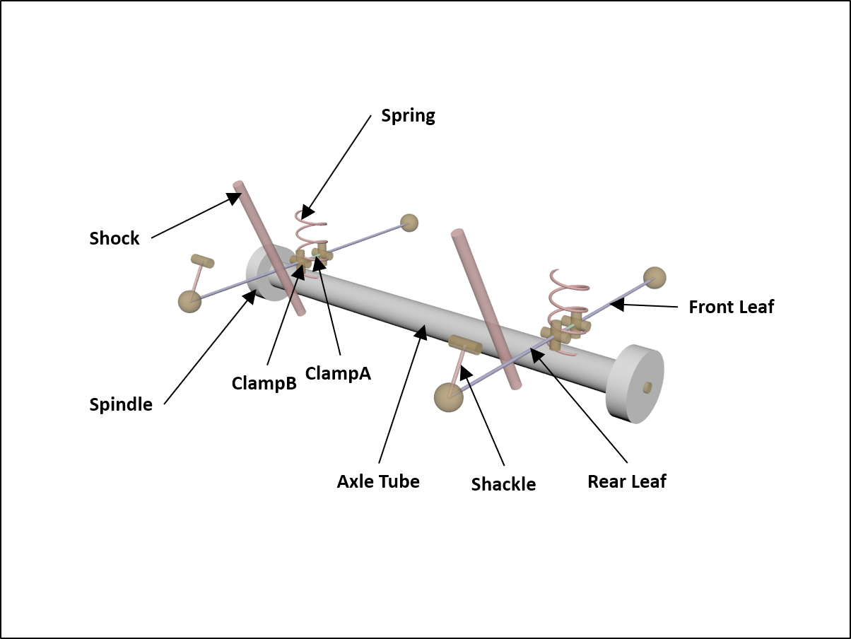
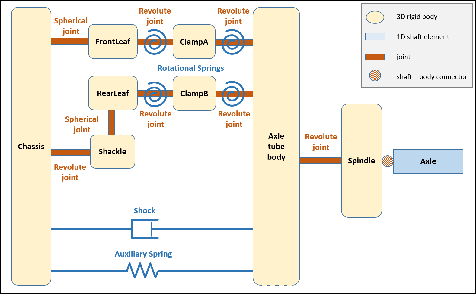
SAE Leaf-spring solid axle
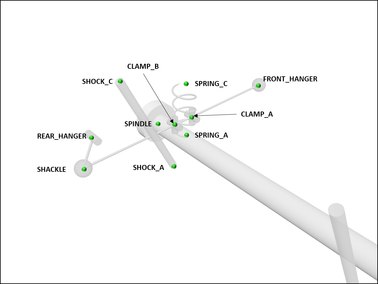
The SAE Spring Design Handbook shows a way to model a leaf spring with realistic deformation behavior under load conditions. The kinematics of a leaf spring can be defined by 5 points. These points can be used to define a leaf spring consisting of 6 rigid bodies (front leaf, front clamp, rear clamp, rear leaf and shackle). The bodies are connected by joints. The rotational springs of the front and rear leaf as well as the front clamp and rear clamp have a rotational stiffness that can be set by the user to define the correct behavior. This suspension is used as a rear suspension on the UAZ vehicle SAE type models. The movement of the axle body due to wheel travel and the tie-up effect due to longitudinal forces can be simulated correctly with this leaf spring model.
See ChSAELeafspringAxle and SAELeafspringAxle.
The topology of this suspension template is:
The hardpoints (defined for the left side only and mirrored to construct the right side) are:
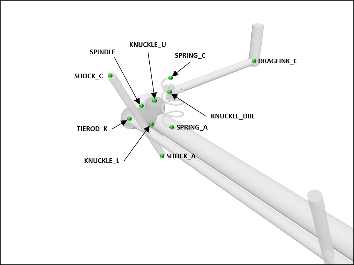
SAE Leaf-spring solid axle with toebar
Used as front suspension on the UAZ SAE type vehicle models. The leaf spring definition is the same as in the SAE leaf spring axle.
See ChSAEToeBarLeafspringAxle and SAEToeBarLeafspringAxle.
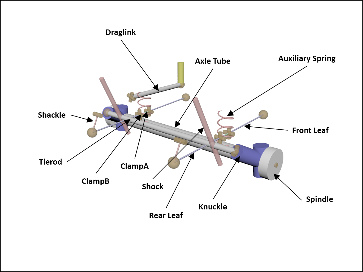
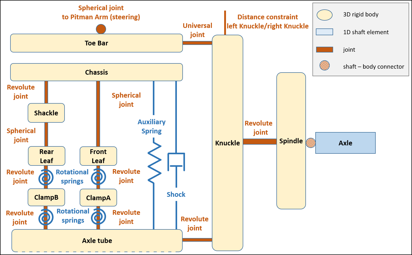
The topology of this suspension template is:
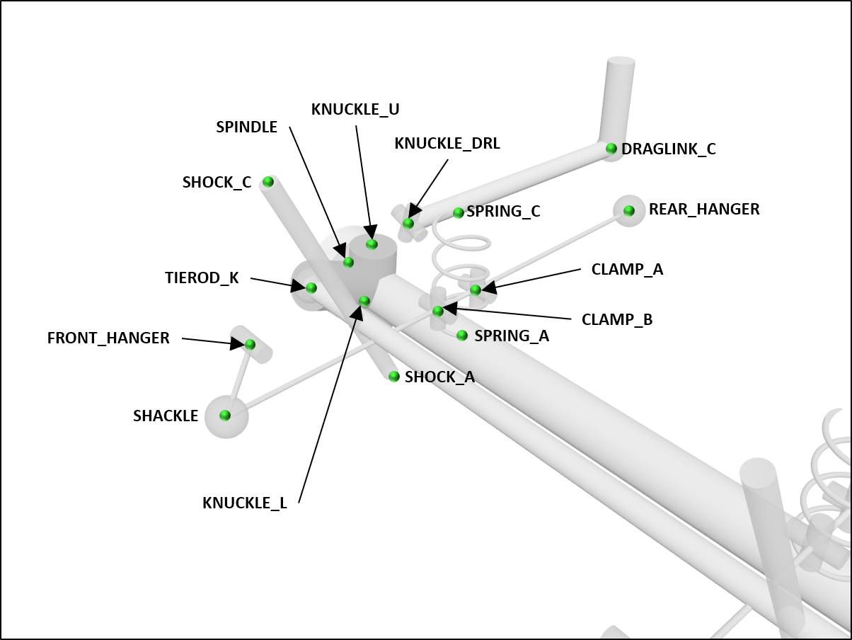
The hardpoints (defined for the left side only and mirrored to construct the right side) are:
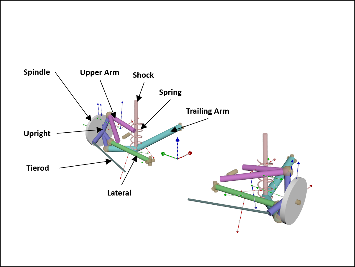
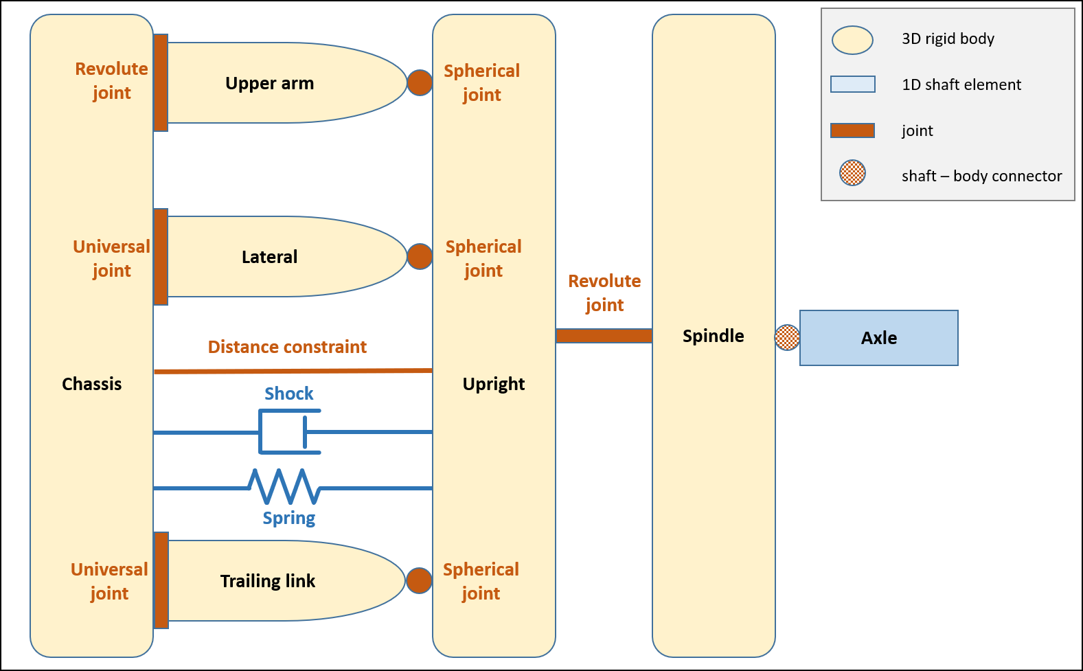
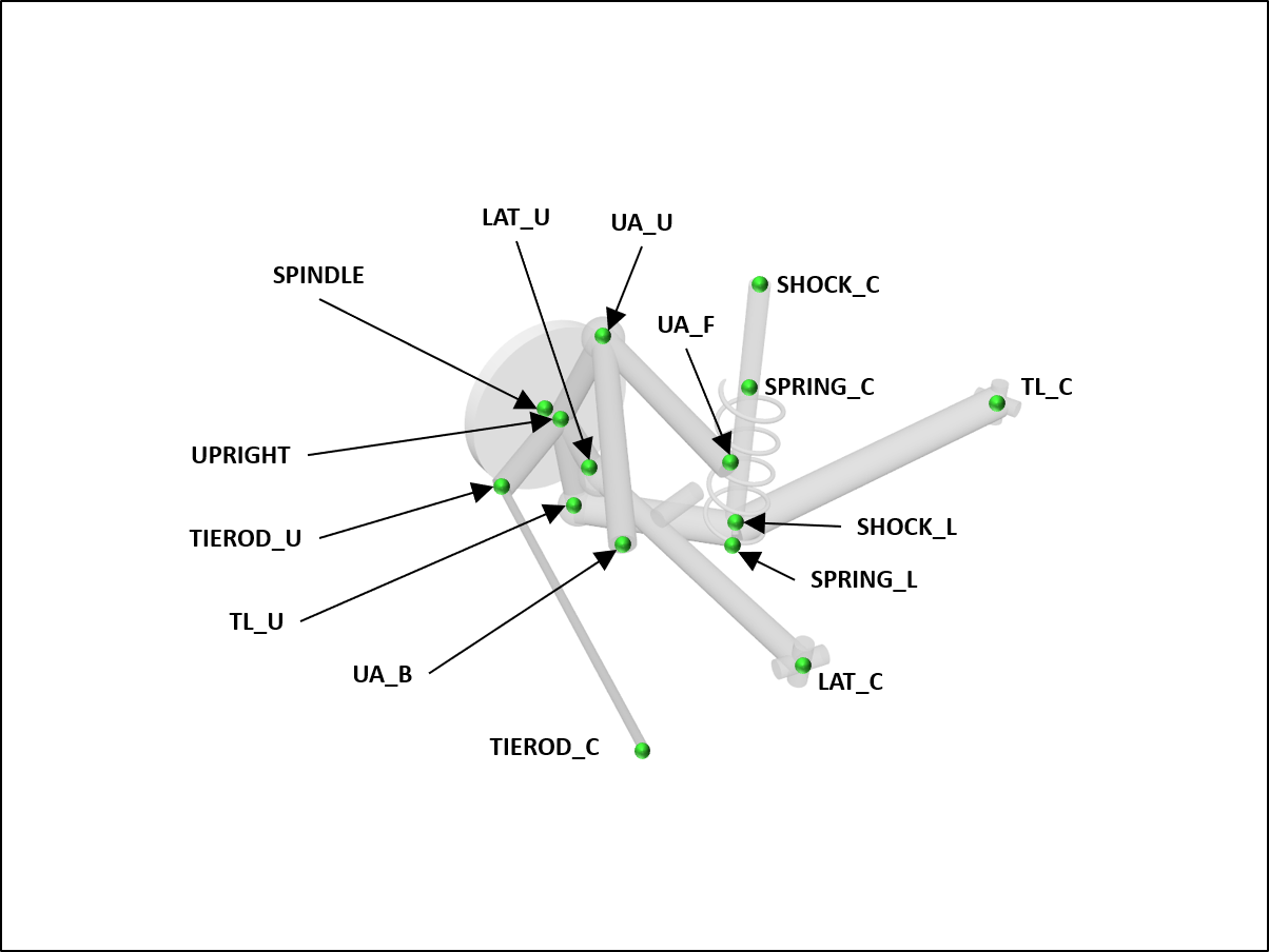
Three-link Independent Rear Suspension
Three-link Independent Rear Suspension (IRS), as seen on the Polaris RZR vehicle.
See ChThreeLinkIRS and ThreeLinkIRS.
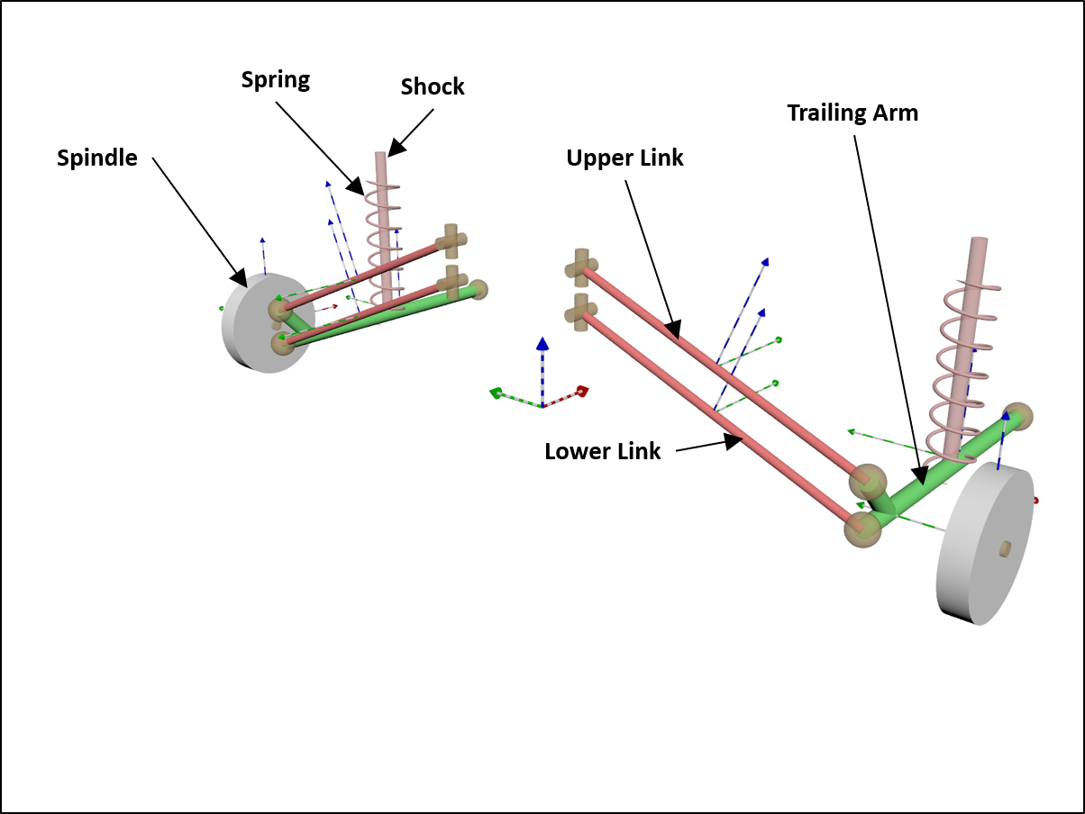
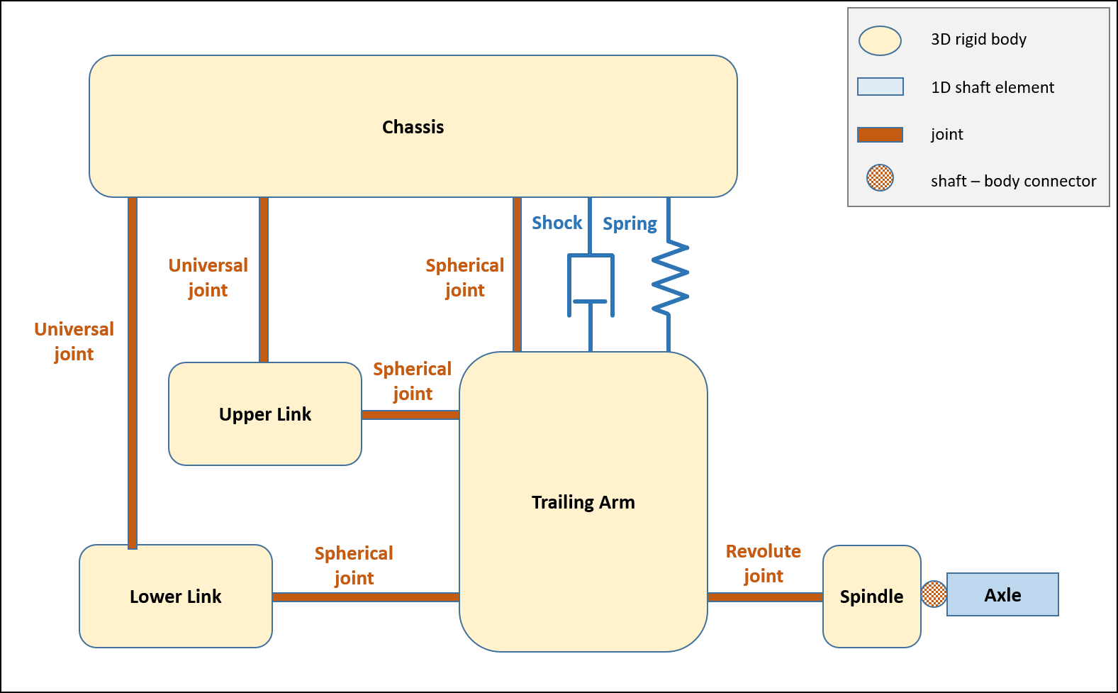
The topology of this suspension template is:
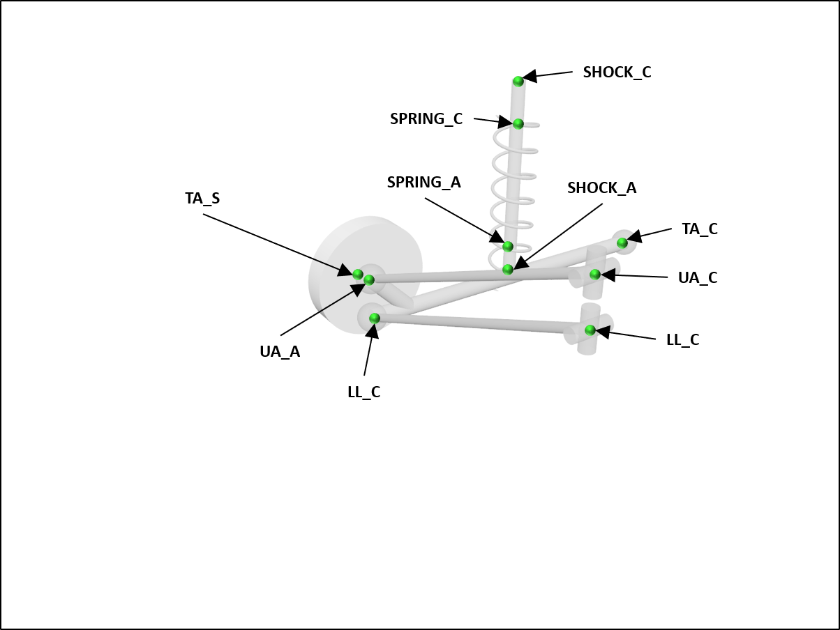
The hardpoints (defined for the left side only and mirrored to construct the right side) are:
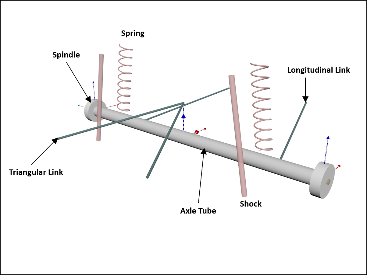
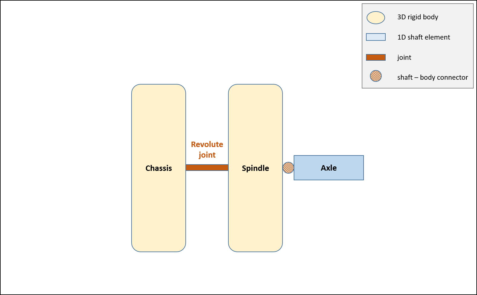
Rigid suspension
Trivial assembly with spindles directly attached to an axle tube pinned to the chassis. It is typical for farm tractors and combine harvesters.
See ChRigidSuspension and RigidSuspension.
The topology of this suspension template is:
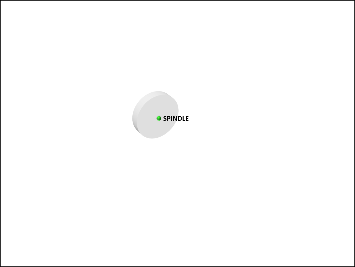
The hardpoints (defined for the left side only and mirrored to construct the right side) are:
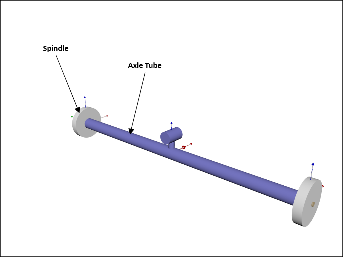
Rigid pinned-axle
Trivial assembly with spindles directly attached to the axle tube that can swing around a pivot point against the chassis. This can be used, if an unsprung axle system is needed but has to run on ondulated terrain to avoid wheel lift off.
See ChRigidPinnedAxle and RigidPinnedAxle.
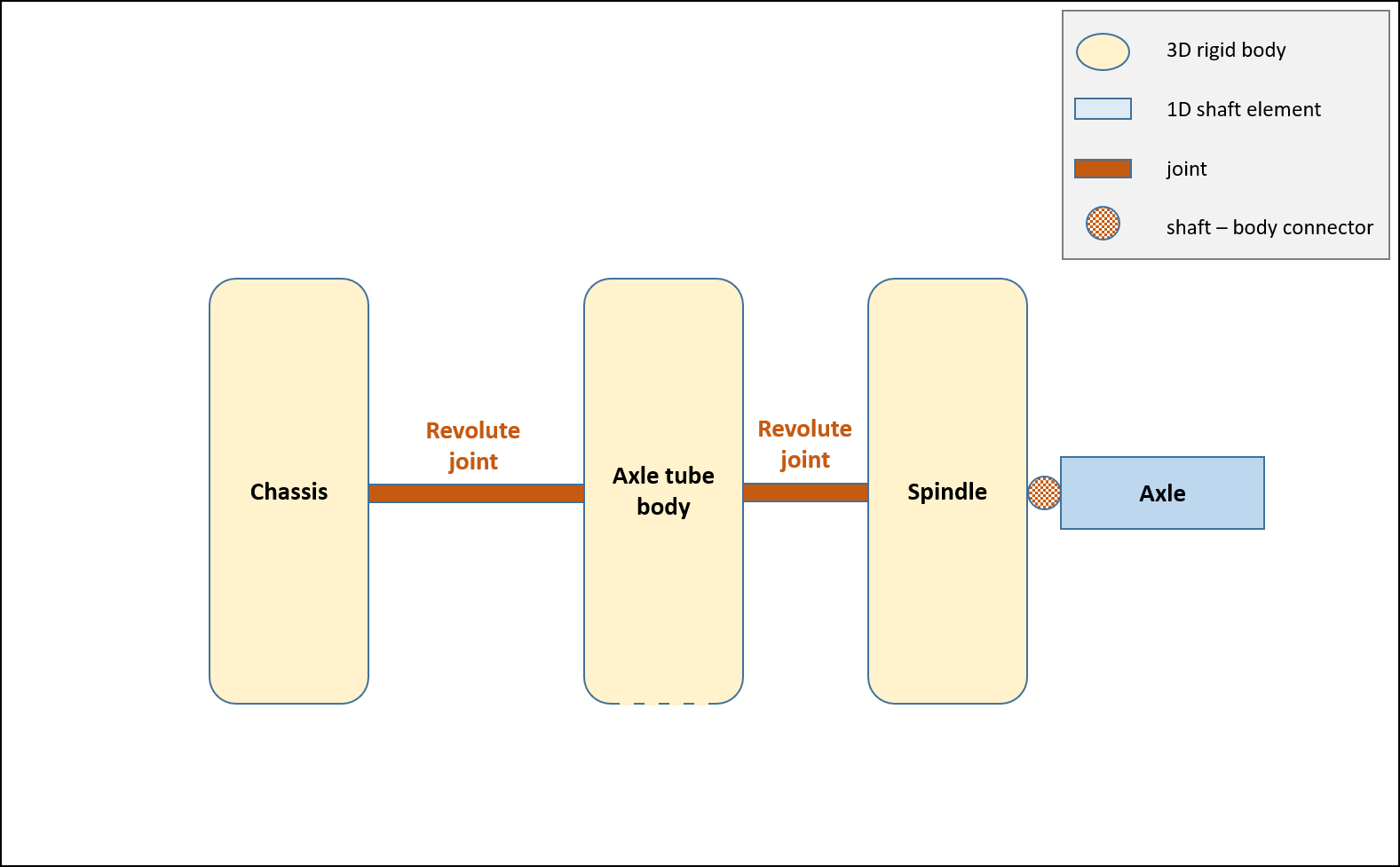
The topology of this suspension template is:
The hardpoints (defined for the left side only and mirrored to construct the right side) are: