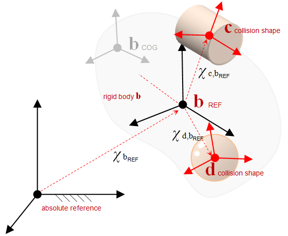
Collision shapes can be added optionally to ChBody objects. Having collision shapes attached to bodies enable them to interact during simulation with other bodies through friction and contact.
Collision models
Each body contains a ChCollisionModel. This can be used to define the collision shapes.

- Collision shapes are defined with respect to the REF frame of the body
- Examples of shapes: spheres, boxes, cylinders, convex hulls, ellipsoids, compounds, etc.
- One can add multiple collision shapes to a rigid body. However, compound shapes will slow down the collision detection phase of the simulation. In this context, there is no geometry simpler to handle than a sphere that is located at the center of mass of the rigid body.
- Handling of concave shapes falls back on a decomposition of the geometry in a union of convex shapes
- For simple ready-to-use bodies that already contain collision shapes, use ChBodyEasySphere, ChBodyEasyBox, etc. (see body manual pages)
- Collision shapes and visualization assets do not need to match; e. g. one may have a detailed visualization shape for rendering purposes, yet the collision shape is much simpler to avoid a slowdown of the simulation.
- Avoid shapes that are too thin, too flat or in general that lead to extreme size ratios
Steps to set up collision after you create a ChBody:
Collision families
You can define collision families for selective collisions. For example you may not want the object of family=2 to collide with any objects of family=4:
Currently, Chrono allows up to 15 different collision families that can be involved in a simulation.
Collision surface materials
Adding collision shapes to a body typically requires the user to define some properties of the colliding surface, e.g. friction, rolling friction, restitution coefficient, etc. This can be set by means of either the chrono::ChMaterialSurfaceNSC or the chrono::ChMaterialSurfaceSMC class.
In fact, Chrono can handle two different contact formulations - Non Smooth Contacts (NSC) and SMooth Contacts (SMC) - each of which requires different surface material types, depending on the chrono::ChSystem in use (see ChSystem manual).
Once the choice has been made, the user can set the surface material properties in these two ways:
Built-in material (Memory consuming)
Each body comes with its own ChMaterialSurface built-in instance, that is automatically created with the body itself and is of type chrono::ChMaterialSurfaceNSC.
The user can access this built-in surface material like this (and similarly for the SMC version):
Please mind that, for this case, each body has its own surface material. This results, for the example above, in three different surface material instances. In case of a large number of bodies this can lead to memory issues. We will see in the next section how to avoid this.
In order to create a ChBody that handles SMooth Contacts (SMC), the corresponding option has to be set during the ChBody construction. For example:
See the chrono::ChBody reference for further details.
Shared material
In some circumstances, different bodies may share the same surface material properties. In this (very common) case, the user can create just one instance of ChMaterialSurfaceNSC (or ChMaterialSurfaceSMC) and share it between different bodies. These bodies will then drop their built-in ChMaterialSurfaceXXX instances.
As we can see, there are a couple of desirable effects:
- only one instance of ChMaterialSurfaceXXX is created in memory, thus limiting the memory footprint;
- the user can set the surface material type ([NSC|SMC]) after calling the body constructor.
However, the user should consider that the properties are actually shared, thus body_d->GetMaterialSurfaceNSC()->SetFriction(0.3); will affect also body_b and body_c.
Collision tolerances
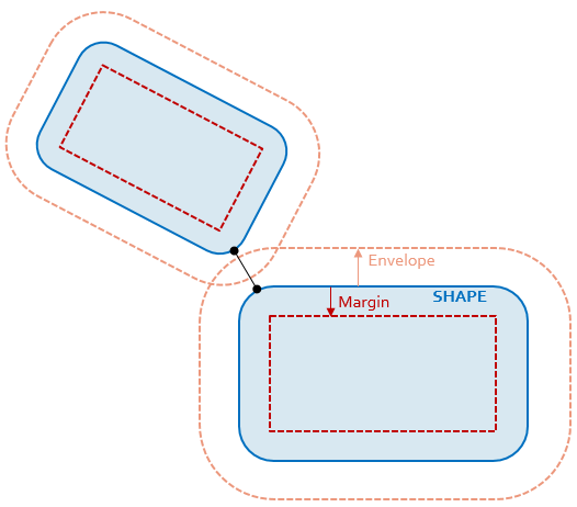
Each collision model has two tolerance used by collision engine to create and delete contacts:
- An outward safe envelope. This represents the volume where potential contacts are searched. In other words, for the sake of collision detection the body becomes puffy, or inflated, by a small amount that is user controlled. Rationale: although at the beginning of a time step two bodies might not be in contact, during the duration of one integration time step they might come in contact. This envelope provisions for this possibility. More specifically, this envelope is needed by the numerical schemes since they must anticipate contacts ahead of time. If these contacts were sent to the solver when objects are already interpenetrating, the motion could be shaky and less accurate. Having a too large envelope will produce a lot of false positives (in terms of contacts), which will slow down both the collision detection and the solution stage. The latter is due to the fact that a lot of contacts will be solved only to produce a `‘zero contact force’' answer.
- An inward margin. Two collision shapes belonging to different bodies might interpenetrate even if considered rigid owing to numerical integration errors, collision detection approximations, ill specified initial conditions, etc. The 'go-to' collision detection algorithm can support interpenetration up to this margin. When this margin is crossed, the solver falls back on a slower collision detection algorithm.
The fast collision algorithm must run between 'shrunk' versions of the shapes, and the original shape is recovered later by offsetting the collision points outward. Hence the rounding effect. In the picture below, the two blue shapes were added as sharp boxes, but the effect from the point of view of collision is like having boxes with rounded corners whose rounding radius is the collision margin.

Drawbacks to poor envelope and/or margin choices:
- Collision envelope too large:
- Many potential contacts
- High CPU time
- Waste of memory
- Collision envelope too small:
- Risk of tunnelling effects
- Unstable, shaky simulation, particularly when dealing with stacked objects
- Collision margin too large:
- Shapes appear too ''rounded''
- Collision margin too small:
- When interpenetration occurs beyond this value, an inefficient algorithm is used
Setting the value of the envelope/margin:
Finally, there is also a contact breaking threshold, which is a global tolerance for all models. It can be set as in this example:
The contact breaking threshold represents the maximum distance between two collision shapes where were in contact before the contact is considered as non-existent. This is due to the fact that Chrono relies in many instances on the Bullet collision algorithms and Bullet keeps contact points persistent from one simulation frame to the next. This threshold value instructs Bullet when to severe the contact between the two collision shapes.
Examples
For further guidance, see:
