This is an important introductory tutorial about how to use the SolidWorks CAD as a preprocessing tool, thanks to the Chrono::SolidWorks add-in.
You will learn how to model a 3D assembly using SolidWorks, how to export it as a .py file containing the Chrono::Engine system description, how to run a Python simulation of the exported system using PyChrono, and how to render the simulation using POVray.
Please follow all steps of the tutorial, once you understood all these steps, you will be able to create a lot of complex mechanisms that can be exported from SolidWorks to Chrono::Engine.
Prerequisites:
- you must have a SolidWorks CAD license.
- the Chrono::SolidWorks add-in must be installed in SolidWorks. Optionally, for the last steps of the tutorial (rendering the animation) these tools must be installed:
- the PyChrono python module must be installed in your Python environment,
- the POVray rendering software must be installed; not mandatory if you want to use the Irrlicht realtime visualization;
- the VirtualDub video editing tool must be installed; not mandatory if you want to use the Irrlicht realtime visualization;
C:/[install path]/chrono_solidworks/examples/engine. The directory contains all the parts needed for this assembly. Create a subassembly
- First, start SolidWorks.
- Use menu: File/New... and choose Assembly.
- If SolidWorks prompts you with a dialog about creating a layout, just close it; we do not need layouts in this tutorial.
Use menu: Insert/Component/Existing Part... and select the
Piston.sldprtfile from the directory of demo files listed above. The piston can be placed where you prefer, in the 3D view: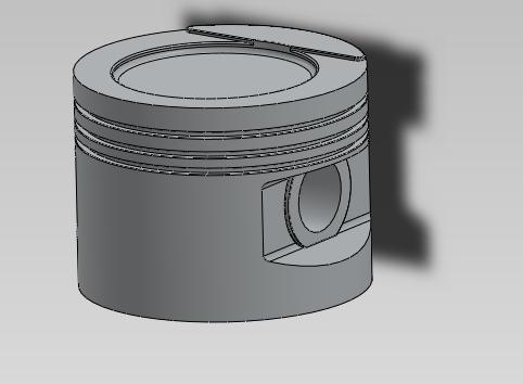
Use menu: Insert/Component/Existing Part... and select the
Conrod.sldprtfile from the directory of demo files. The piston can be placed where you prefer, in the 3D view: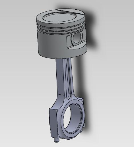
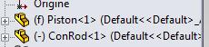
The Feature Manager view, at the left, should look like this:
- Use the Mate tool to create constraints between the piston and the conrod. This tool can be accessed easily by pushing this button:

The mating tool should be familiar to all users of SolidWorks, it consists in selecting a pair of surfaces and setting which type of constraint should be enforced between them; press the green checkmark button when done:
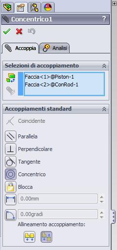
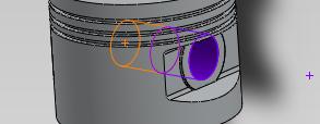
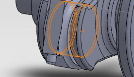
In detail, you must create a Concentric mating between the rod and the piston, like in this figure...
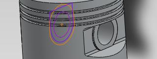
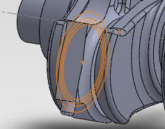
...and a Coincident mating between the rod and the piston, like in this figure:
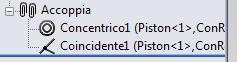
Created constraints can now be seen in the Feature Manager view, at the left:
- Use menu: File/Save As... and save this assembly as
piston_rod.sldasm, in the directory that you prefer. This subassembly (piston + rod) will be used later as a building block for making a larger assembly of the entire motor.
Create the root assembly
- Use menu: File/New... and choose Assembly. Now we will make the root assembly, that contains the entire motor. An assembly can contain parts or sub-assemblies too.
- Again, if prompted for the creation of a layout, just skip it by closing the layout dialog.
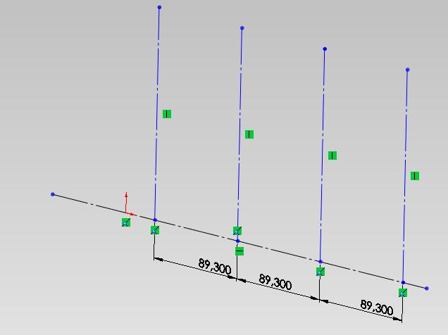
- Select the front plane by selecting it in the Feature Manager and clicking Sketch in the resulting popup menu, so that we can create a few reference axes on it.
In the sketch, create the following scheme with an horizontal axis and four perpendicular axes, and add dimensions so that you are sure that they are separated by 89.3 mm:
Use menu: Insert/Component/Part... and select the
Crankshaft.sldprtfile from the directory of demo files.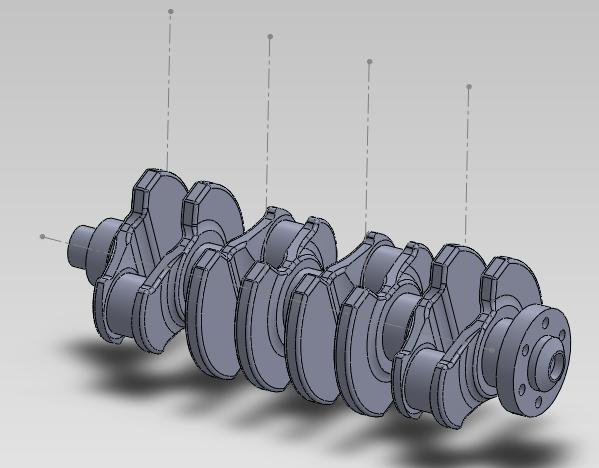
- Note that in the Feature Manager view, at the left, the name is shown as with the{(f)}where the ```(f)``` label means that this part is fixed. By default, the first part that is inserted in SolidWorks is fixed; but in our case we want it to be free because we will take care of constraining it to a revolute joint, so use the popup menu in the Feature Manager and change from *Fixed* to *Floating*, so you will see```(-) Crankshaft <1
(-)label. Use the Mate tool to create constraints between the crankshaft and the horizontal axis. Use the button:
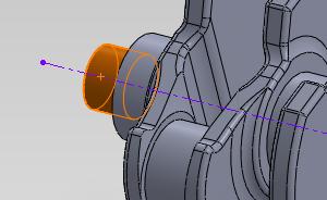
The constraint should be of Concentric type:
- Use menu: Insert/Component/Assembly... and select the
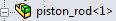
piston_rod.sldprtfile that you saved previously (or use the one provided in the demos directory). Place the subassembly in the 3D view. - Note! the subassembly, by default, will be handled as a rigid assembly (that is, the piston and the conrod cannot be articulated) and this is not the desired behavior. The fact that the subassembly is rigid can be seen by looking at its icon:
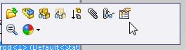
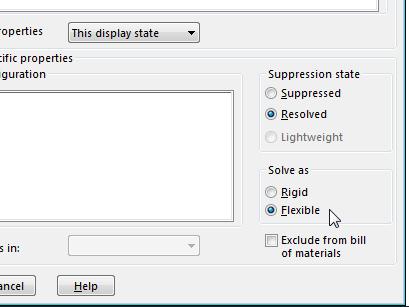
So, now use the popup menu and use the Properties button, shown in this picture:
Now, in the window that opens, switch from Solve as.. Rigid to Solve as.. Flexible:
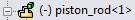
Press Ok and close. You will see that the icon has changed into:
- Use the Mate tool to create constraints between the crankshaft and the conrod. Use the button:
- You must create a Concentric constraint and a Coincident constraint:
- Use the Mate tool to create constraints between the piston and the vertical axis that you created in the sketch. Use the button:
You must create a Concentric constraint:

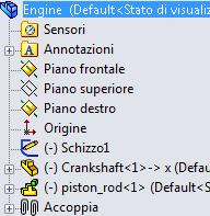
Note that, finally, the hierarchy of your assembly should look like this:
- Use menu: File/Save As... and save this assembly as
engine.sldasm, in the directory that you prefer. (note that a ready-to-use assembly with this name is already given for your convenience if you want to skip the previous steps of the tutorial).
Export the assembly as a Chrono::Engine system
Open the tab of the Chrono::Engine exporter, at the right of the view window:
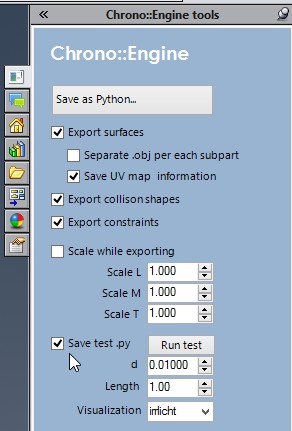
- Check the Save test.py button (this will generate an example Python script that computes a simple animation and outputs data that can be postprocessed for rendering).
- Press the Save as Python... button and save as
engine.pyin an empty directory.
This operation will save the entire root assembly as a Python file, called engine.py, that contains lot of statements that, once executed as a Python module, will create many ChBody objects for all the moving parts in SolidWorks, and many ChLink objects for each SolidWorks mating constraint. Use an editor to inspect the engine.py file so you can get an idea of what happened.
Aside to the engine.py exported file, there will be a directory called engine_shapes. Look into that directory: you will find three .obj files, each corresponding to a 3D mesh with the visualization shape of the moving parts. These shapes will be used later by the Chrono::Engine postprocessing system if you want to do a rendering of the simulation.
You can also modify, edit or simplify these .obj meshes using 3D tools such as Blender
Run a Chrono::Engine simulation in an interactive 3D view
Since you enabled the Save test.py option, a test.py program that loads and simulate the engine was automatically generated for you. You can run it directly from SoliWorks for a quick test, do this:
- Check the Visualization Irrlicht option, to use a 3D realtime view
- Press the Run test button.
At this point the test.py will load the engine.py model and show this interactive view, that you can pan&zoom with the mouse while the simulation is running:
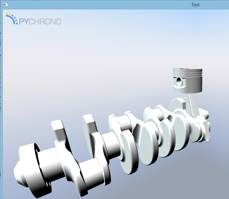
That is!
Note, do not expect to see a lot of movement in this animation: the only motion will be caused by the weight of the piston that will make the crankshaft swing a bit. If you want to impose a continuous rotation, you need to follow the following tutorial,Demo_engine advanced.
How is this working?
What is happening under the hood? When you press Run test:
- SolidWorks calls the Python interpreter that will run the test.py file, based on PyChrono;
- on its turn, the test.py file will:
- load the engine.py file that you exported from SolidWorks
- put all objects of engine.py into a ChSystem object
- setup a simple visualization system based on Irrlicht
- run the simulation loop
Note that on some systems the step 1 could fail if the Python interpreter is not available on a global path. If so, you can start test.py by hand, by opening for example an Anaconda shell and launching it with:
Anyway: the test.py file is just a simple stub. You can use it as an inspiration and modify it for creating a more sophisticated Python program. We strongly suggest to open it in your Python IDE editor and see how it is working.
Run a Chrono::Engine simulation using POVray
- Check the Visualization pov option, to use POVray as a postprocessing rendering tool
- Press the Run test button.
The simulation will be computed with no interactive view: wait few seconds. At the end of the simulation, you will find that the directory of engine.py has been populated with additional files; some of them are generated by the postprocessing system of Chrono::Engine. Proceed as follows:
- Open POVray.
- Drag and drop the
rendering_frames.pov.inifile into POVray window. Press the Run button in POVray.

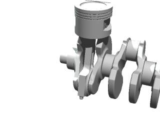
A series of .bmp images will be generated with raytracing, and saved in the anim directory:
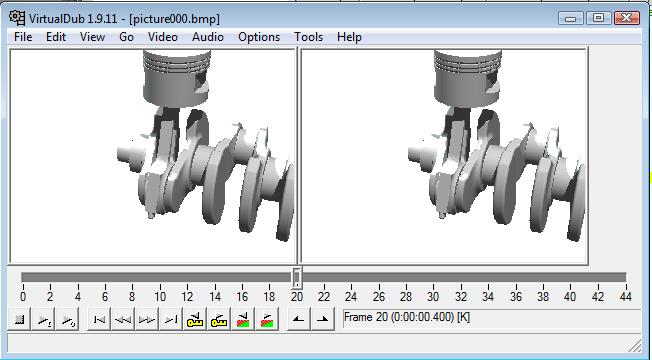
To generate an animation starting from a sequence of .bmp files: just start the VirtualDub tool and load the first image of the sequence, all others will be automatically added:
- It is suggested that you choose a proper compression codec, in VirtualDub. To do so, use the menu Video/Compression... and configure the codec. We suggest a Mpeg4 / DivX codec. Maybe you need to install a codec pack if the Mpeg4 is not yet installed on your system.
- Also, remember that you might need to set the frame rate, that usually is 25 or 30 frames per second. Just use the menu Video/Frame rate...
- Finally Save as AVI.
Proceed to a more complex system
Optionally, you can repeat this exercise by adding more cylinders, to create a complete four cylinder engine:
Add three other
piston_rod.sldasmsubassemblies and create the proper constraints (avoiding creating redundant constraints); you should get this:
- Save the entire assembly as
engine4c.sldasm - Export the Chrono::Engine system as
engine4c.py
This done, now you can proceed with the following Demo_engine advanced where you will learn advanced topics about how to add additional constraints (ex. a motor constraints that imposes the rotation of the crank), how to change the rendering look of the shapes, etc.