The Chrono::Vehicle module provides a collection of templates for various topologies of both wheeled and tracked vehicle subsystems, support for modeling rigid, flexible, and granular terrain, support for closed-loop and interactive driver models, and run-time and off-line visualization of simulation results.
Modeling of vehicle systems is done in a modular fashion, with a vehicle defined as an assembly of instances of various subsystems (suspension, steering, driveline, etc.). Flexibility in modeling is provided by adopting a template-based design. In Chrono::Vehicle, templates are parameterized models that define a particular implementation of a vehicle subsystem. As such, a template defines the basic modeling elements (bodies, joints, force elements), imposes the subsystem topology, prescribes the design parameters, and implements the common functionality for a given type of subsystem (e.g., suspension) particularized to a specific template (e.g., double wishbone). Finally, an instantiation of such a template is obtained by specifying the template parameters (hardpoints, joint directions, inertial properties, contact material properties, etc.) for a concrete vehicle (e.g., the HMMWV front suspension).
The core templates in Chrono::Vehicle are parameterized models of vehicle subcomponents. However, a complete vehicle mobility simulation also requires auxiliary systems, external to the vehicle itself, such as a driver system to provide input controls (e.g., steering, throttle, braking), a powertrain system which encapsulates the engine and transmission and connects to the the vehicle driveline, and a terrain system.
For wheeled vehicle systems, templates are provided for the following subsystems:
- suspension (double wishbone, reduced double wishbone using distance constraints, multi-link, solid-axle, MacPhearson strut, semi-trailing arm, ...)
- steering (Pitman arm, rack-and-pinion)
- driveline (2WD and 4WD shaft-based using specialized Chrono modeling elements, simplified kinematic driveline)
- wheel (simply a carrier for additional mass and inertia appended to the suspension's spindle body)
- brake (simple model using a constant torque modulated by the driver braking input)
Chrono::Vehicle offers a variety of tire models and associated templates, ranging from rigid tires, to semi-empirical models (such as Pacejka and Fiala), to fully deformable tires modeled with finite elements (using either an Absolute Nodal Coordinate Formulation or a co-rotational formulation).
For tracked vehicles, the following subsystem templates are available:
- track shoe (single- and double-pin)
- associated sprocket templates (with corresponding gear profiles)
- suspension (torsional spring with either linear or rotational damper, hydraulic)
- idler (with tensioner mechanism)
- rollers
As a middleware library, Chrono::Vehicle requires the user to provide C++ classes for a concrete instantiation of a particular template. An optional Chrono library provides complete sets of such concrete C++ classes for a few ground vehicles, both wheeled and tracked, which can serve as examples for other specific vehicle models. While such classes are typically very lightweight, this requires some programming experience. To address this issue, we provide an alternative mechanism for defining concrete instantiation of vehicle system and subsystem templates, which is based on input specification files in the JSON format.
Following the hierarchy of subsystem templates for its given type (wheeled or tracked), a vehicle can be completely defined through a corresponding hierarchy of JSON files that specify the concrete template parameters or else defer to further JSON specification files for sub-components. The following is an example of a top-level JSON specification file for a wheeled vehicle. Together with all other input files it refers to, this JSON file completely describes a concrete wheeled vehicle with two axles, using double wishbone suspensions both in front and rear, a Pitman arm steering mechanism attached to the front axle, and a rear-wheel driveline.
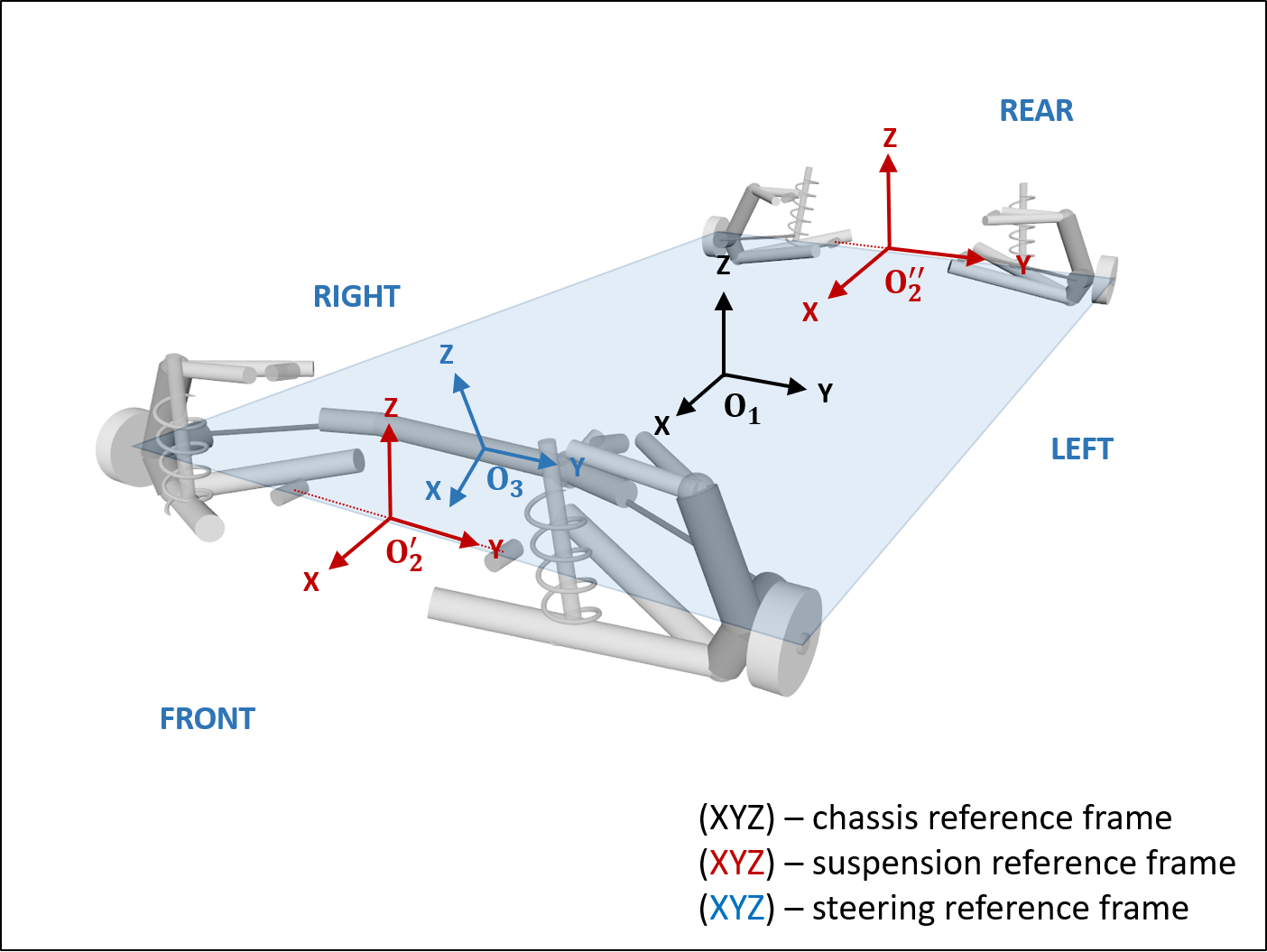
Reference frames
Each vehicle subsystem is defined with respect to its own reference frame; in other words, all hardpoint locations in a vehicle subsystem template must be provided with respect to the subsystem's reference frame. A vehicle system, be it wheeled or tracked, is then constructed as a collection of concrete instantiations of templates for its constituent components by specifying their position and orientation with respect to the vehicle reference frame and providing connectivity information, as required (e.g., attaching a particular steering mechanism to a particular axle/suspension of a wheeled vehicle).
For modeling, Chrono::Vehicle uses exclusively the ISO vehicle axes convention, namely a right-hand frame with X forward, Z up, and Y pointing to the left of the vehicle (see ISO 8855:2011). The figure below illustrates the vehicle reference frame O1 (by convention aligned with that of the chassis subsystem), as well as subsystem reference frames (O'2 and O''2 for the front and rear suspensions, and O3 for the steering mechanism) for a wheeled vehicle with two axles.
Simulation world frame
While the default world frame for Chrono::Vehicle simulations is also an ISO (Z up) frame, support is provided to simulate vehicles in a scene specified in a different reference frame (for example, an Y up frame). The world frame is uniquely defined through a rotation matrix (the rotation required to align the ISO frame with the desired world frame). To change the world frame definition from the default ISO convention, the desired world frame must be set before any Chrono::Vehicle library call:
A shortcut is provided to specify a world frame with Y up (and X forward, Z to the right):
The ChWorldFrame class provides utilities to query the world normal, forward direction, the height of a given 3D point (component along the world's vertical direction), to project a point onto the world's horizontal plane, as well as to express a 3D vector to and from the base ISO frame.
See demo_VEH_HMMWV9_YUP for an example of a Chrono::Vehicle simulation in an Y up world frame.
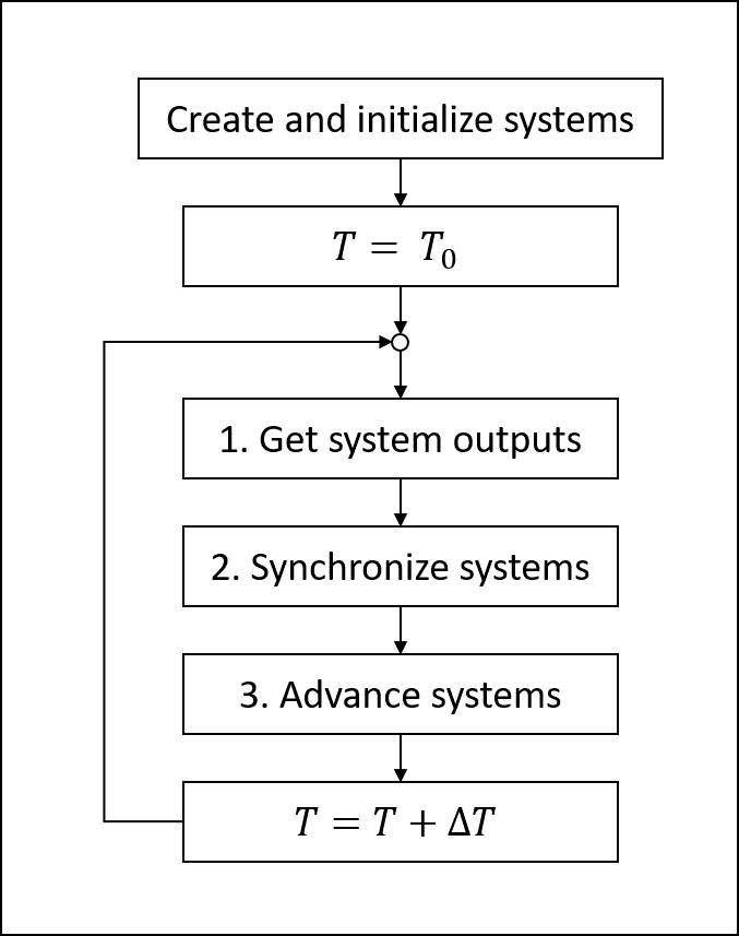
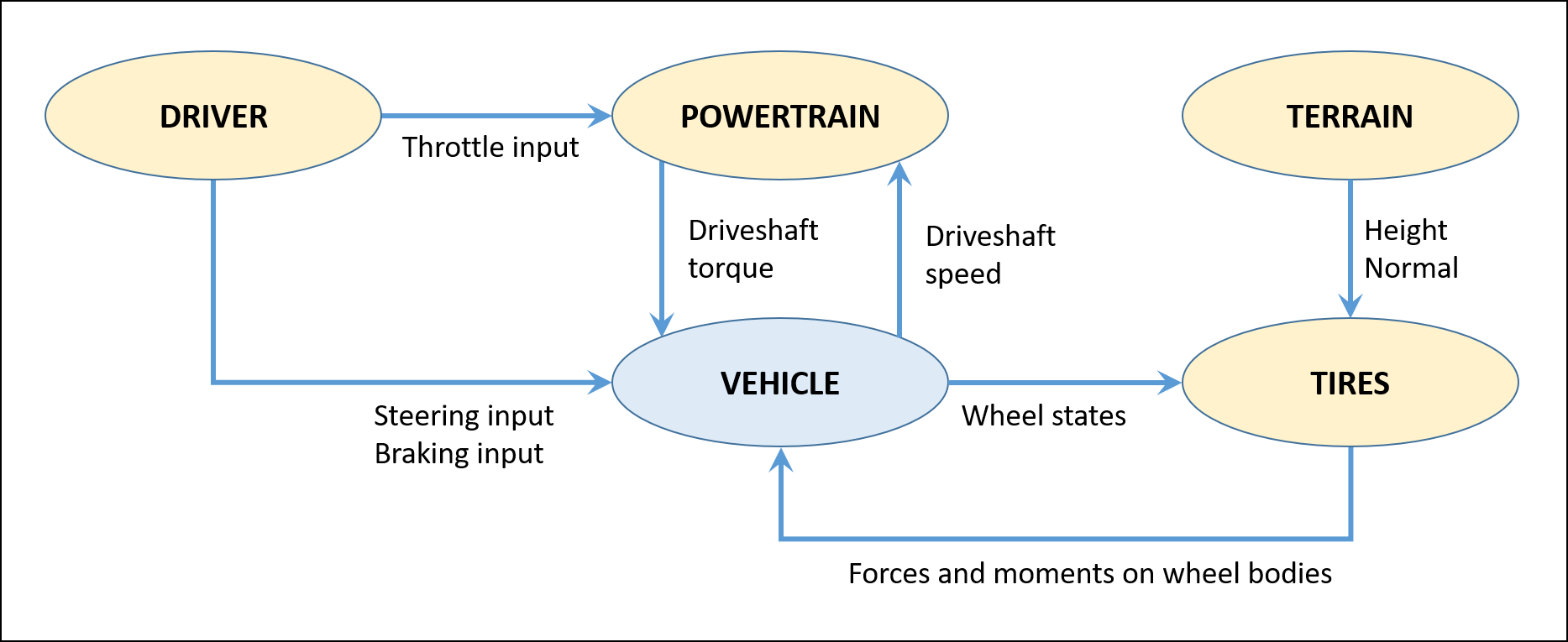
Simulation loop
A Chrono::Vehicle simulation loop takes the form of a force-displacement co-simulation scheme, with the exchange data illustrated in the two figures below for wheeled and tracked vehicles, respectively.

This software architecture was adopted in order to
- provide modularity and flexibility;
- permit use of third-party auxiliary system models and integration of Chrono::Vehicle models in larger simulation frameworks;
- enable co-simulation with external tools or with other Chrono modules.
This simulation flow is enforced through the Chrono::Vehicle API which imposes that all systems provide a Synchronize method, which implements the data exchange, and an Advance method, which implements the system dynamics (i.e., advances the system's states to the next data exchange time point). Note however that a vehicle mobility simulation that uses auxiliary systems provided within Chrono::Vehicle will actually be a monolithic, all-at-once coupled simulation.