Table of Contents
Driver inputs (steering, throttle, and braking) are provided from a driver subsystem with available options in Chrono::Vehicle including interactive, data-driven, and closed-loop (e.g., path-following based on PID controllers).
The base class for a driver system, ChDriver, imposes minimal requirements from a driver system template, in particular the ability to return throttle input (normalized in the \([0,1]\) range), steering input (normalized in the \([-1, +1]\) range, with a negative value indicating steering to the left), and braking input (normalized in the \([0,1]\) range). In addition, a driver system can receive information from any other system (e.g., the vehicle state) through its Synchronize method and may have internal dynamics (implemented in its Advance method). Specific templates for a driver system may extend the set of vehicle inputs generated, for example including the current selected gear for a manual transmission, enabling/disabling the cross-drive capability on a tracked vehicle, etc.
Chrono::Vehicle includes several templates for driver systems. For interactive simulations, run in soft real-time, it provides a template for a driver system which produces the vehicle inputs based on user controls, either keyboard and mouse, or a game controller.
For design of experiment simulations, it provides a driver system template that is based on inputs provided through a text data file, with the vehicle inputs obtained through linear interpolation. Such data files can also be automatically generated by data collected during interactive runs.
Finally, Chrono::Vehicle includes several closed-looped driver system models, based on underlying support for PID controllers. These include speed controllers (which adjust the throttle and braking input simultaneously to maintain a constant vehicle speed) and path-follower controllers. The latter adjust the steering input so that the vehicle follows a user-defined path specified as a Bezier curve.
Interactive driver
The interactive driver ChInteractiveDriver (for both the VSG- and Irrlicht-based run-time visualization systems) can control (steer/accelerate/brake) a simulated vehicle through user input. These interactive drivers rely on keyboard and controller event handlers for the respective run-time visualization systems.
Other features of this driver subsystem model include:
- experimental controller support
- ability to lock/unlock driver inputs to their current values (controlled through key
J) - ability to record and playback user inputs (using an embedded data-based driver; see below)
Keyboard driver
- key
Aincreases left turn steering wheel angle - key
Dincreases right turn steering wheel angle - key
Waccelerate - key
Sdecelerate
The throttle and braking controls are coupled, in the sense that acceleration first drives braking to zero before increasing throttle input (and vice-versa for deceleration).
Controller driver
Modern simulators commonly have multiple (USB) devices for all the different control elements in a car. They come with devices for pedals, a wheel, an H-shifter, a sequential shifter, a handbrake and a button box (with tons of buttons to change in-car systems). Chrono supports this by being able to assign controller axis and buttons to multiple devices attached. Axis can also be calibrated, setting the minimum and maximum (raw) value for that axis as well as the intended (scaled) output values.
Mapping and calibration are done using a "controller.json" file in the data/vehicles folder that allows you to assign controls to axis and buttons of those “controllers”. We ship a couple of examples of such files, but typically you need to customize this file to your own setup:
controller_XboxOneForWindows.jsonis a fairly standard controller setup that should be easy to adapt for most users, it maps all axis and include a sequential shifter setup as well as a way to toggle between automatic and manual gearboxes.controller_WheelPedalsAndShifters.jsonis an example of a more complex, multi-controller setup, featuring a steering wheel, three pedals, as well as both a sequential and H-shifter setup. This example probably needs extensive modification if you want to use it, but it shows how different controllers can be used.
Example controller file
At the top level of the file, we have a collection of controller functions (steering, throttle, shiftUp, ...) and for each of these we can specify either an axis or button definition with all the mapping details:
- Axis:
steering,throttle,brake,clutchhave the following attributes:nameis the name of the controller on the system;axisis the number of the axis you want to map to;minandmaxare the raw minimum and maximum values of this axis;scaled_minandscaled_maxare the output minimum and maximum values of this axis;
- Buttons:
shiftUp,shiftDown,gearReverse,gear1,gear2, ...,gear9,toggleManualGearboxhave the following attributes:nameis the name of the controller on the system;buttonis the number of the button you want to map to;
A word about controlling the gearbox:
- There is support for sequential shifters if you have a manual gearbox. You can toggle between automatic and manual gearboxes with another button.
- There is also H-shifter support. The code supports up to 9 forward gears and has support for shifting (as long as you have the clutch fully pressed down).
There is also a debug mode that will, twice per second, print all the values of the axes and buttons of all connected controllers. This comes in handy when you're defining a file and probably should be disabled otherwise.
Limitations of the current implementation
- All controller handling is linked to IrrLicht which means you need to use that for visualisation. It also means we inherit all the limitations of how IrrLicht handles controllers. This is mainly reflected in the number of buttons per controller that are supported, but other limitations might also exist.
Data-based (open-loop) driver
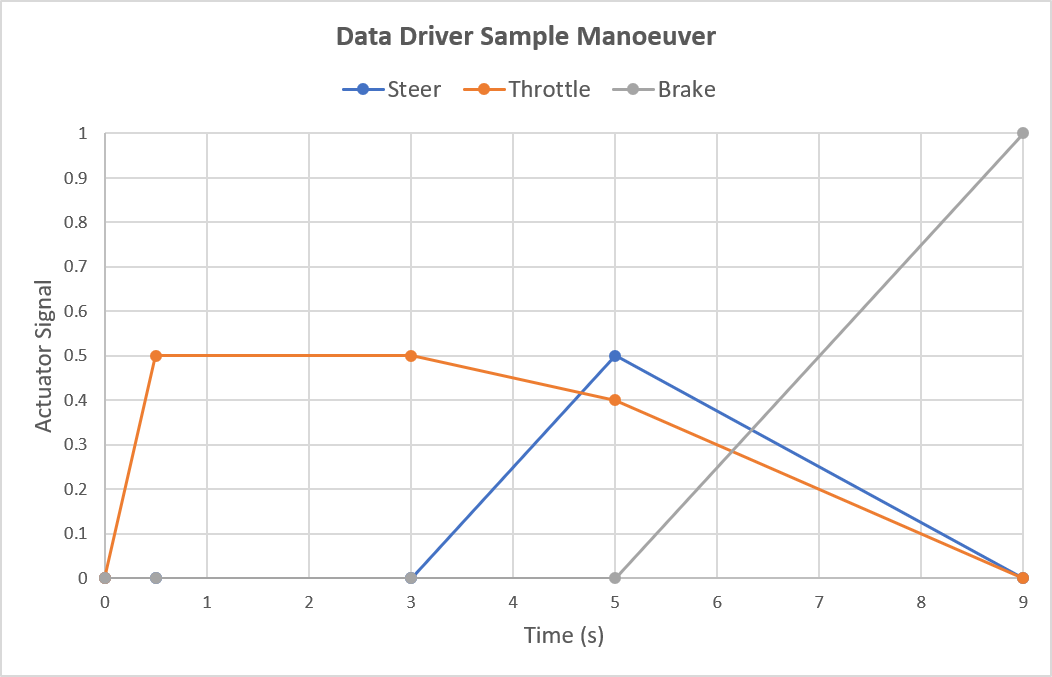
Some important vehicle test maneuvers are based on time-dependent steering/throttling/brake signals. No feedback of any kind is considered. This driver model is implemented in ChDataDriver.
An ASCII data file with driver inputs contains four columns, for time (s), steering input (a non-dimensional quantity in \([-1,1]\), with \(-1\) indicating full steering to the left), throttle input (a non-dimensional quantity between \([0,1]\), with \(1\) indicating full throttle), and braking (a non-dimensional quantity between \([0,1]\), with \(1\) indicating full braking force).
A sample driver data file is listed below

At any given time, the current driver inputs (steering, throttle, and braking) are obtained by piece-wise linear interpolation of the provided data. Beyond the last time entry, driver inputs are kept constant at their last values.
Close-loop driver models
Close-loop driver models need a control strategy and consider feedback. Feedback can lead to instable behavior, so the controller parameters have to be chosen wisely. The example parameters have been working in a wide range of use. The user should start with one of the given example parameter sets and only modify it if necessary.
Path-follower controller
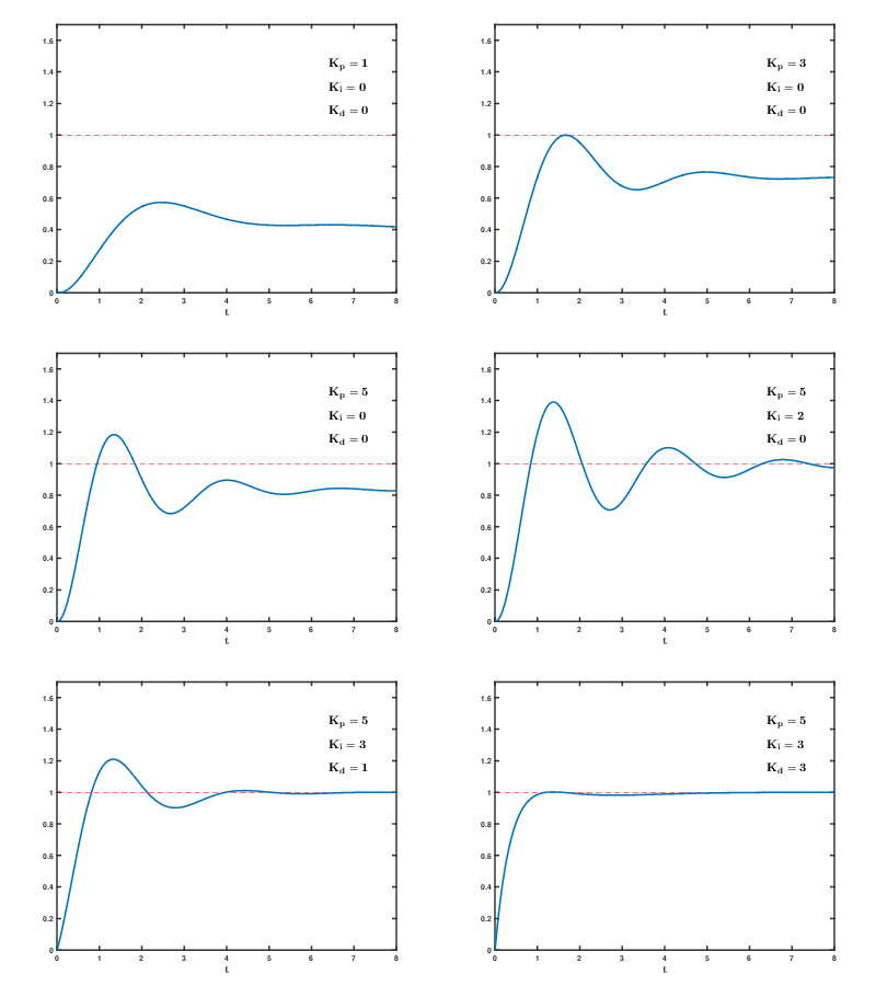
To make the vehicle follow a given path it is necessary to measure the lateral path deviation and to generate a steering wheel angle that minimizes the deviation. A well known solution for this problem is the PID controller (P=proportional, I=Integral, D=Differential). Taking the pure P variant one only needs to set the P-gain. This will work in many cases but pure P controllers can never reduce the lateral deviation to zero. The residual deviation decreases with increasing P-gain. If the P-gain is too large, the vehicle begins to oscillate around the demanded vehicle path. A residual path deviation can be eliminated by setting the I-gain to a value of around 5% to 10% of the P-gain. By setting the D-gain it is possible to apply damping if a path oscillation occurs. If the I-gain is used, the simulated maneuver should not take longer than about 2 minutes. If it takes more time, the controller states should be reset every 2 minutes to avoid instabilities.
The next chart (Wikipedia) shows how Chrono implements the PID controllers:

- r(t) = demanded path signal
- e(t) = lateral path deviation
- y(t) = actual path signal
- u(t) = steering signal
This chart (Wikipedia) shows the influence of the gain factors:

A human driver does not only react on deviation changes, he is able to anticipate. In Chrono this ability is simulated by taking a reference point for measuring the deviation in front of the vehicle body. The distance of the reference point from the vehicle reference system is called look-ahead-distance and is an important controller input parameter.
The desired path is specified as a Bezier curve (see ChBezierCurve). The error is defined as the deviation between a "sentinel point" (a point located at the look-ahead distance in the vehicle forward direction) and a "target point" (the projection of the sentinel point onto the desired path).
Constant-speed controller
To maintain a given vehicle speed the PID controller can be used. The difference to the path controller is that it uses a speed deviation instead of the lateral path deviation.
- r(t) = demanded speed signal
- e(t) = speed deviation
- y(t) = actual speed signal
- u(t) = throttle/brake signal
The class ChPathFollowerDriver implements the PID lateral controller in combination with a PID speed controller. It works well at extreme maneuvers like double lane change.
An interesting alternative for standard road driving maneuvers is ChPathFollowerDriverSR. It has a PID speed controller but takes lateral control strategy that considers human and vehicle properties. The anticipation uses look-ahead time instead of a look-ahead distance which means the effective look-ahead distance varies with the speed.
Optimal-speed controller
The constant-speed controller is good for many standard driving maneuvers. For driving on a long and curved road it is interesting how fast the vehicle can negotiate the whole course. For cases like this the ChHumanDriver class has been developed. Both the lateral and the speed controllers use human behavior, vehicle properties, and anticipation as well as field of view of the driver. The lateral controller is identical to the one implemented in ChPathFollowerDriverSR.
