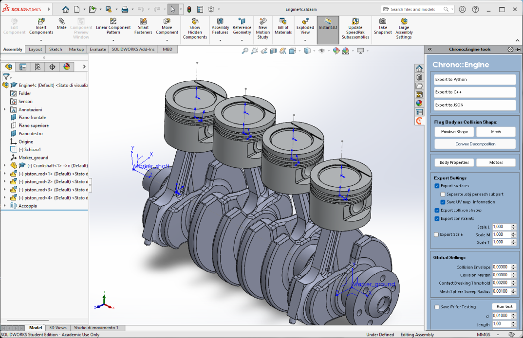
Chrono::SolidWorks is an add-in for SolidWorks that allows to export SolidWorks models directly into Chrono.
The tool allows to:
- export entire Assemblies, nested SubAssemblies and Parts, together with their material and appearance properties;
- export Mates of the Standard type plus Mechanical>Hinge;
- specify collision shapes, both through primitives or by automatic generating a contact mesh shape from the objects;
- add Chrono motors, together with their control functions;
The SolidWorks model can be exported to:
- Python: can be run by PyChrono or parsed in C++ through the Chrono::Parsers module (still, in this case, PyChrono needs to be installed);
- C++: the generated files needs to be compiled together with the user project; it might be limiting but very useful for testing;
- JSON: this allows the deserialization of the model through the Chrono serialization feature;
The fastest way to consume the output of the SolidWorks add-in is by using the dedicated template project that can be found in the add-in repository. It is also a good source of information on how to load the exported models in the various cases.
Usage
Once installed (see the dedicated installation guide) a new icon with the Chrono logo should appear in the SolidWorks Task Pane (i.e. the vertical set of icons on the right side of the SolidWorks display). All the following actions are performed through this panel.
Some prior information should be known to successfully export the model:
- run the export only from Assemblies, not from single Parts;
- each SubAssembly is considered as a single rigid body, unless it is set as Flexible;
- Chrono motors are specified through Coordinate Systems objects that must be placed at top level (not inside Parts);
- objects do not collide by default;
- collision is set on Solid Bodies, not Parts;
- the creation of Primitive collision shapes will convert the material of the selected body to Air;
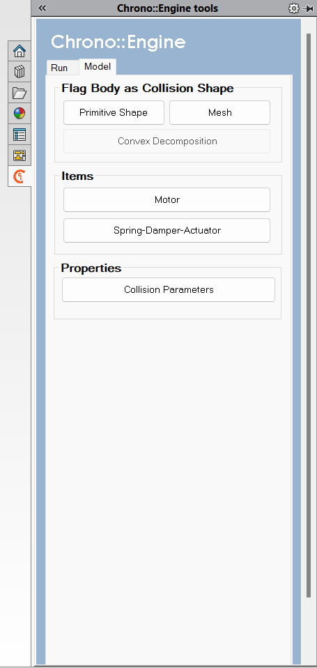
Adding Collision Shapes
Collision detection and contacts simulation are usually among the most expensive actions to be performed in a simulation. Because of this, only those bodies that are specifically flagged as "collidable" will be taken into consideration by collision algorithms.
For the same reason is good practice, whenever possible to wrap complex bodies into primitive shapes by creating an additional simple body around the object. The material of this wrapping object is then automatically set to Air.
To enable collision on a body:
- select a Solid Body (not a whole Part): expand the Part tree, look for Solid Bodies, pick one of them;
- expand the Chrono::SolidWorks add-in by clicking on it;
- choose between different collision shape types, in this order:
- Primitive Shape (the lightest to compute): if the body resembles a primitive shape (box, sphere, cylinder, etc.) this is automatically recognized and attached to the body; moreover, the selected body will be set to be of air material and its appearance will be changed to semi-transparent;
- Mesh: most of the bodies fall into this category, where the shapes are not so simple as primitives; a mesh is automatically generated; however, better performance can be achieved by replacing it with a hand-tailored mesh in postprocess; less robust than primitive shapes; a sphere sweep (of radius Mesh Sphere Sweep Radius) will happen on bodies, thus "inflating" the original shape for what concerns collisions; the bigger the radius, the more robust, but the less accurate will be the collision detection;
- Convex Decomposition: to be implemented...
After flagging the body to become a collision shape, a custom label will be prefixed to the solid body name. Do not modify such prefix. Moreover, please mind that the Part itself will be affected. So, all instances will be enabled to collision.
Some collision settings are available at the bottom of the panel.
Please be aware that this action cannot be undone by just clicking Undo.
Adding Motors
Chrono motors can be added directly to the SolidWorks model by placing a Coordinate System (in Assembly tab > Reference Geometry). This will act as a placeholder where a proper ChLinkMotor will be later placed during the export phase.
To add a Chrono motor:
- expand the Chrono::SolidWorks add-in by clicking on it;
- click on Motors;
- the panel will offer various choices: pick the appropriate motor together with its governing function (see the relative manual on how to use them in Chrono);
- select a Coordinate System from the tree view and click on Add marker; the Coordinate System must be at the top-level
- select a Part from the tree view and click on Add slave body; do the same for the master body;
- click on Create motor.
A custom property will appear as a child item of the selected Coordinate System. By selecting it and then clicking on the Motors > Select Marker button it is possible to retrieve, edit or delete the motor properties. Note: this custom motor property is transparent to versions of Solidworks that do not have the Chrono::Solidworks Add-in installed.
Customize Settings
Some settings are self-explanatory. For all of them the tooltip will offer some basic information. Here a description of those more intricated:
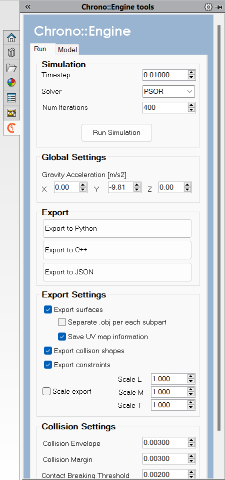
- Separate .obj for each subpart: Parts or SubAssemblies that consist of multiple solid bodies can generate either a mesh file for each single object or a unique mesh that includes them all;
- Export Scale: the model can be scaled prior to export through the appropriate setting: please mind that the add-in automatically recognize the units used in SolidWorks and takes care of transforming them into SI units without any further change. This scaling options are only to provide an additional scaling on top of the typical one.
- Run Simulation: a Chrono simulation of the assembly can be run directly in Solidworks environment, without the need of additional coding; useful for tests before exporting the model to file.