Table of Contents
Please read the demo engine tutorial before proceeding with this.
Therefore we assume that you already created run_test.py for the four-cylinder engine, using the Chrono::SolidWorks add-in exporter that creates such PyChrono files.
In the following, you will learn how to modify the run_test.py program that was automatically generated by the exporter, in order to customize the simulation and add advanced functionalities.
Now, the idea is that you can write a more sophisticated Python program to make more advanced simulations; for example you can add springs, dampers, motors, particles, etc. Also, you can modify properties of objects that were saved by the add-in exporter, for example you might want to override the mass properties of some part.
- To spend less time, just copy the
run_test.pyfrom the demo engine tutorial and rename it asrun_test_modified.py. We will work on this file as a template. - Open
run_test_modified.pyin your Python IDE (for example, Spyder). Read PyChrono introduction if you are new to Python programming for Chrono::Engine.
Now we are ready to do various modifications to the Python program; here are some ideas.
C:/[install path]/chrono_solidworks/examples/engine. The directory contains all the parts needed for this assembly. The scene loading code
The unmodified run_test_modified.py program can be run from the shell as run_test_modified.py -f engine4c.py, but if you remove the argument parsing section and add the import statements above, you can run it from the IDE or by simply double-clicking on it, without the need of specifying the -f parameter.
Example: suppose you exported your engine mechanism as engine4c.py. In order to import that Chrono::Engine mechanism in your Python code, write:
engine4c, not engine4c.py. That is, no .py suffix must be used here. Also note that the ./ path must be specified even if the file was in the current directory. Note how all exported items are added to a ChSystem:
Add additional coordinate frames
If you want to add additional bodies/constraints/springs etc. via programming, it can be helpful if you can use xyz coordinate frames as references. You can add these coordinate systems using SolidWorks, then export them as .py files, and later fetch their position and rotation. For example, here we see how to use a coordinate system to define the Z axis of a ChLinkEngine motor that we will add between the crank and the ground, later.
- First of all, add a SolidWorks feature of CoordinateSystem type, using the menu Insert/reference geometry/Coordinate system.
Select the beginning of the sketched axis in the assembly, as origin, and select the direction of that axis as Z direction of the coordinate system feature. You should get something like this:
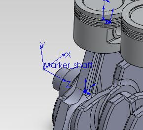
- If all is working correctly, the coordinate system will be added into the assembly (do not add it into subassemblies or parts, we do not need so in this example).
Change its name into something mnemonic, in our example we changed it to
Marker_shaft.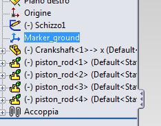
- Save the assembly with the Save as Python button, exporting it again to Chrono::Engine as
engine4c.py. - Now in your
run_test_modified.pyyou can fetch that coordinate system as a ChMarker object! Just use theSearchMarkerstatement:Once you got the marker as a Python object, for example, you could get its absolute position withmy_marker = my_system.SearchMarker('Marker_shaft')if not my_marker :sys.exit('Error: cannot find marker from its name in the C::E system!')my_marker.GetAbsCoord().pos.x, etc. For instance, in the next paragraph we will use it to create a constraint in a specific position.
If you have a doubt about the name of an exported object, just open the exported .py file (engine4c.py in our case) and look where you read lines like this: ....SetName("blabla");
Add more constraints (an engine)
The engine4c.py, as exported by SolidWorks, does not contain any constraint that enforces the rotation of the crankshaft; the only constraints that are exported are the 'mating' constraints such as the revolute joints between the crank and the rods, etc. etc.
Here is an example of how to create an additional constraint, namely, a rotational engine between the crankshaft and the ground. Once you learned this, you will be able to extend this concept to other types of constraints.
- Fetch the ground body and the crankshaft as Python objects. You can do this thank to the fact that they have unique mnemonic names: ground (default name for the assembly root), and Crankshaft-1 (the name of the crankshaft part). Hence, do: my_shaft = my_system.SearchBody('Crankshaft-1')if not my_shaft :sys.exit('Error: cannot find shaft from its name in the C::E system!')my_ground = my_system.SearchBody('ground')if not my_ground :sys.exit('Error: cannot find ground from its name in the C::E system!')
- Finally, add this bit of code to create a constraint of ChLinkMotorRotationSpeed type, that is a link that constraints the rotation of two parts; the two parts are the two rigid bodies that you just fetched, my_shaft and my_ground: revolute_frame = my_marker.GetAbsFrame()link_motor = chrono.ChLinkMotorRotationSpeed()link_motor.Initialize(my_shaft, my_ground, revolute_frame)link_motor.SetSpindleConstraint(chrono.ChLinkMotorRotationSpeed.SpindleConstraint_CYLINDRICAL)link_motor.SetMotorFunction(chrono.ChFunction_Const(1.0*chrono.CH_C_2PI)) # 1.0 Hz to rad/smy_system.Add(link_motor)
The Initialize() function requires two bodies and a ChFrameD object that represents the position and rotation of the constraint; we'll use the frame of my_marker. In this case the ChLinkMotorRotationSpeed constraint assumes that the Z axis of the frame is used for the rotation axis.
Although you could create a ChFrameD from scratch, by typing the rotation and xyz position values, here it was smarter to use the frame of the my_marker object that was created in SolidWorks and fetched in the previous paragraph.
The SetSpindleConstraint() is a custom function of ChLinkMotorRotation classes: it can be used to choose which type of connection is used between the two parts. Here we want to set a constant angular velocity, ex. one turn per second, and then we need SetMotorFunction() to pass a ChFunction object, that is a ChFunction_Const in this case.
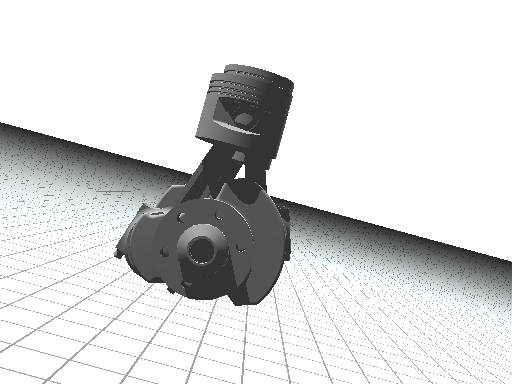
After you modified the run_test_modified.py according to the suggestions above, you can run it (from your IDE or by double-clicking on it). You should be able to see the four-cylinder engine spinning in the 3D Irrlicht interactive view, as in this picture:
Improving the POVray rendering
As an alternative to the Irrlicht interactive view, you can use the POVray batch rendering of the simulation. If you look in run_test_modified.py, you can see that the default behavior is using Irrlicht, but you can easily switch to POVray by changing a line at the top of the listing, from
to
and the rest of the code will use the POV postprocessor, with a placeholder code that you can freely modify, or take inspiration from.
Change camera viewpoint
If you want to change the viewpoint of the camera for the POVray postprocessing system, look in run_test_modified.py for the following statement and modify the x y z coordinates of the viewpoint to your needs. The parameters of SetCamera() are the vector with the position of the observer viewpoint, the vector with the position of the aim point, and finally the degrees of the lens angle (ex. 30° for tele lenses, 50° for a wide lenses, etc.):
Change material of shape visualization
Maybe that your 3D rendering looks too dull because all surfaces, by default, look like white chalk. However you can pich one object and change its appearance by tweaking the POVray materials. The idea is that you can add additional objects of ChAsset type into each moving part; one of these ChAsset objects could belong to the ChPovRayAssetCustom class, that allows you to add optional POVray statement to the rendering scripts that are generated for a specific shape. Look how this is achieved by using this bit of code:
In this case we created a fragment of POVray statements, namely a definition of a pigment and a glossy metallic finish, and we assigned it to the my_shaft object (that we already fetched, using the method described in the previous paragraphs).
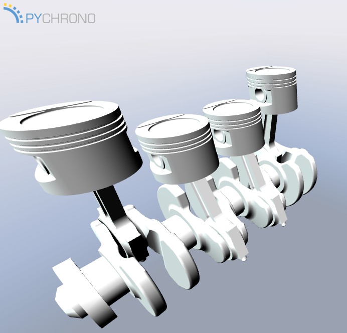
Now run again run_test_modified.py: it will create again the .pov and .ini scripts,so you can load again the .ini file into POVray and render the animation; you should be able to see that the crankshaft looks metallic:

Note that we also generated a horizontal plane and a grid: this can be done by adding additional POVray statements that act on a global scale; here is the piece of code:
Setting all objects as transparent
Suppose you want to set the material of all objects in the scene: this can be done by iterating on all objects as in this piece of code, where we want to set all parts as 80% transparent:
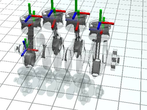
Show constraint coordinates
In the previous paragraph we set all objects as transparent; this can be useful in case you want to render the position of the reference coordsystems of the constraints -this can be seen as a 'visual debugging' of the simulation...
The code that you need to enable rendering coordinate systems of constraints in POVray postprocessing is this:
Show Centers of Mass
Suppose you want to visualize the Center Of Gravity (COGs, also known as centers of mass) of each ChBodyAuxRef body: this is the code that you need:
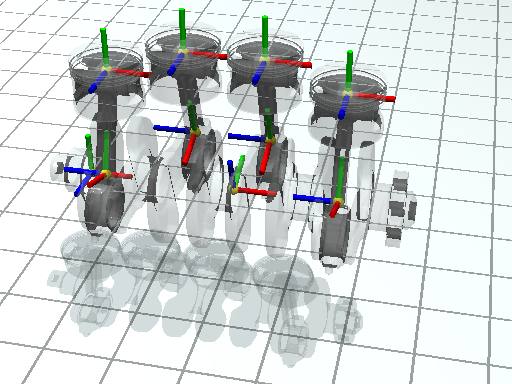
The center of mass is computed automatically by SolidWorks when you export the mechanism to the Chrono::Engine .py file, and depends on the density of the materials that you assigned to the parts in SolidWorks interface.
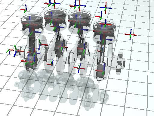
Show coordinate frames
Suppose you want to visualize the reference coordinate sytems of each ChBodyAuxRef body: this is the code that you need:
Note that the bodies that are exported from the SolidWorks Add-in are not of the simple ChBody class, but rather they belong to the advanced ChBodyAuxRef class. In fact, while ChBody objects assume that their center of mass is coincident with the reference coordsystem of the body, whereas in ChBodyAuxRef bodies the body's reference coordsystem usually is distinct from the center of mass.
Important: the reference coordinates of the moving bodies are displayed as origins in the SolidWork interface (where x y z planes intersect). Each part in SolidWorks has an origin. If multiple parts are merged in a SolidWorks subassembly that is solved as rigid (see previous tutorial), then the reference coordinate of the moving body is the origin of the subassembly.
Attach a camera to a moving object
Suppose you want to make an animation where a camera is moving together with a simulated part, for example you might want to show the point ov view of a driver that sits on a vehicle. This can be accomplished with the following piece of code:
- First, fetch an object by looking at its name; for example here we choose one of the four rods because we want to render an animation where the point of view is moving together with a rod:
- Now, create a
ChCameraasset, set its position and aimpoint in the coordinate system of the conrod and add it to other assets of the conrod:
When you render the animation you should see something like this: