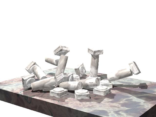
This tutorial shows how to use the Chrono::SolidWorks add-in for assigning collision shapes to SolidWorks parts. Those collision shapes will be converted to Chrono::Engine collision shapes when exporting the .py scene file.
Note that, by default, all parts that you model in SolidWorks do not generate any collision shapes: if you want to simulate phenomena with collisions, you must use the procedure that is outlined in this tutorial in order to assign collision shapes to parts. This is motivated by various reasons:
- you can choose to add collision shapes only to parts that really need them, thus reducing the computational overhead;
- currently there is no automatic way to convert generic detailed concave shapes into a set of Chrono::Engine collision shapes (actually, a tool for automatic convex decomposition is under development, but in many cases the best results come when the user add convex shapes by hand)
Currently, the following convex shapes are supported:
- spheres
- cylinders
- boxes
- convex hulls.
Also groups of them are supported.
Prerequisites:
- you must have a SolidWorks CAD license.
- the Chrono::SolidWorks add-in must be installed in SolidWorks. Optionally, for the last steps of the tutorial (rendering the animation) these tools must be installed:
- the PyChrono python module must be installed in your Python environment,
- the POVray rendering software must be installed; not mandatory if you want to use the Irrlicht realtime visualization;
- the VirtualDub video editing tool must be installed; not mandatory if you want to use the Irrlicht realtime visualization;
C:/[install path]/chrono_solidworks/examples/collisions. The directory contains all the parts needed for this assembly. We are going to model a small set of columns with capitals, that will be shaken by an earthquake.
Create a column
- First, start SolidWorks.
- Use menu File/New... and create a new Part.
- In the Part editor, create a doric column (like those that you can find in Greek temples) by using the
 Revolved boss / base tool in the toolbar. (Just create a profile like a rectangle, where one of the vertical sides is rather an almost flat arc, and the opposite side is the axis of revolution).
 You should obtain this:
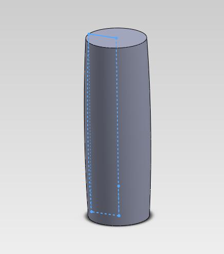
This shape will be used for computing the mass, the tensor of inertia, the coordinates of the part, and also the visualization mesh if you are using POVray or other types of postprocessing, but it won't produce any collisions yet! Therefore, now we assign a collision shape to this part.
Collision shapes that can be converted to Chrono::Engine .py files are of simple types: spheres, cylinders, boxes, etc (or compounds of them). So now we will approximate the column with a single cylinder, assuming the at this level of approximation is enough for the simulation that we want to do.
To add a collision shape, we exploit a possibility of SolidWorks: each part can contain more than a single 'shapes' - those shapes are called solid bodies in SolidWorks (not to be confused with the concept of rigid bodies in Chrono::Engine).
So, we will create an additional cylindrical body: use the tool
 Extruded boss / base and extrude a disc from the top of the column to the top of the column.
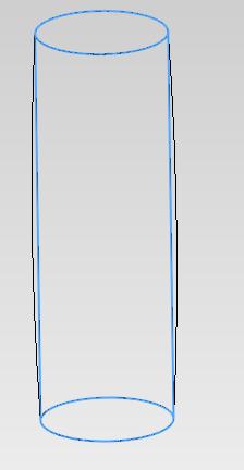
Important! before accepting the result of the extrusion, uncheck the Merge results option!
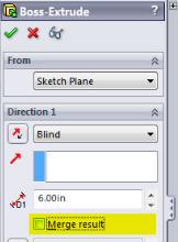
Thanks to the unckecked Merge results option, now you can see that you have two bodies in the left panel (if you forgot this, by default SolidWorks will merge the cylinder with the column and you still get a single body because they are overlapping).

Select the second body (the cylinder) and use the tool Set body as collision shape in the Chrono::Engine add-in tab, at the right of the screen.
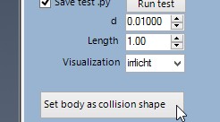
This tool detects that your selected body is a cylinder, so it marks it as a collision shape; note that the name of the body changes, and you get something like this:

- Save it as
column.sldprt.
Create a capital
- First, start SolidWorks.
- Use menu File/New... and create a new Part.
In the Part editor, create a box with a square base, using the
 Extruded boss / base tool. (This is the basic shape that we will engrave later to make a detailed capital).
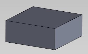
Now we show another way to define a collision shape: select the box solid body and use the menu Insert/Features.../Copy... , be sure that Copy is selected, and accept the tool without moving anything.
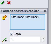
Now you have two copies of the initial box: one of them will be used to represent the collision shape. Select the second body and use the tool Set body as collision shape in the Chrono::Engine add-in tab, at the right of the screen.

You should get this:

Now proceed by adding details to the other body (not the collision shape, that can also be hidden to make things easier). For example, use the
 revolved boss tool and add a toroidal shape like this:
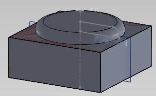
- We want to add a collision shape that represents the torus: a cylinder is sufficient to this end. Create a cylinder (do not forget to uncheck the Merge results option!), select it, use the Set body as collision shape in the Chrono::Engine add-in tab, as you learned in the previous steps.
You may want to add optional details such as bevels, etc., so you get the following result:

that is
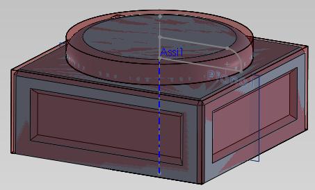 =
= 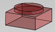 +
+ 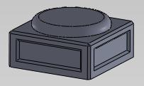
Note that in this case you defined the collision shape with a group of different collision primitives, namely a cube and a cylinder. You can add as many collision shapes as you want in a single part.
Create the floor
- Use menu File/New... and create a new Part.
- Following the instructions previously described for creating the capital, you should be able to create a large flat box, assign a box collision shape to it, and save it as
floor.sldprt(in our example files on disk, we savedfloordirectly inside the assembly portal.sldasm).
Assembly the building
- Use menu File/New... and create a new Assembly.
- If SolidWorks prompts you with a dialog about creating a layout, just close it; we do not need layouts in this tutorial.
- Use menu: Insert/Component/Part... and select the floor part to add it to the assembly as a fixed part
- Be sure that it shows as
(f)floorin the Feature Manager, not as a floating(-)floorpart. In case, use the popup menu as learned in previous tutorials. - Use menu: Insert/Component/Part... and select the capital.sldprt part.
- Use the
 Mate tool to place the capital perfectly laid on the floor.
 Repeat the last two steps to add also the column.sldprt part on the top of the capital, and repeat again to add capital.sldprt on the top of the column. Add mate constraints to have them perfectly aligned:
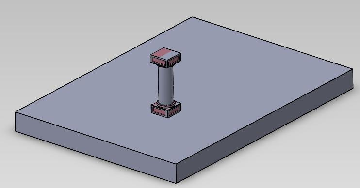
Now deactivate the mate constraints, because we do not want them to be exported into the .py Chrono::Engine file (if you keep them active, you will get a building that cannot fall down during the earthquake). To deactivate them, simply select them and use the popup menu
 ; they will turn 'ghosted':
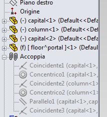
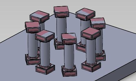
If you want, you can create an array of columns by selecting lower capital column higher capital and use the circular array tool
 . This will produce the following result:
Export the assembly as a Chrono::Engine system
Export the system as you learned in previous tutorials: open the tab of the Chrono::Engine exporter, check the Save test.py button, press the Save as Python... button and save as
collisions.pyin an empty directory.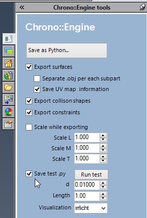
- If you press the Run test button, the test Python script will compute the simulation. Just a static scene.
However, there are three points to improve here: columns will stay fixed because there is not yet any earthquake, the camera view frustrum might not be properly aligned to show all columns, and surface materials might look too dull and boring. In the next steps we will modify the simulation by writing a customized Python script.
Custom Python simulation, introducing earthquake
- Copy the run_test.py file and rename it as
run_test_modified.py. We will work on this file as a template. - Open run_test_modified.py in your Python IDE (for example, Spyder).
- Although is not mandatory, it is wise to set the inward and outward collision envelopes of the collision detection algorithm. This is epecially important for very large or very small objects. Note, this must be put before importing the models and/or creating the ChSystem. chrono.ChCollisionModel.SetDefaultSuggestedEnvelope(0.005)chrono.ChCollisionModel.SetDefaultSuggestedMargin(0.005)
- Modify the section that loads the .py system file as: exported_items = chrono.ImportSolidWorksSystem('./collisions')
- Create a contact surface material (surface data that will be used by collision detection to know the friction coefficient and other properties in contact points). In this example, there is a single contact surface material to share between all objects. brick_material = chrono.ChMaterialSurfaceNSC()brick_material.SetFriction(0.6)
Also note that for materials with compliance you should no collision safe envelope, i.e.:
chrono.ChCollisionModel.SetDefaultSuggestedEnvelope(0) Note also that nonzero restitution coefficient is not physically accurate except for very simple scenarios, because it is based on the very simple Newton restitution assumption.
- Assign the brick_material to all rigid body objects, by iterating over all items in the ChSystem: for my_body in my_system.Get_bodylist():my_body.SetMaterialSurface(brick_material)
- For a better look in the animation, assign a marble procedural texture to all objects. This is done by creating a ChPovRayAssetCustom object, that contains a custom statement in POVray syntax, that will be used when the POV postprocessor will produce the POV scripts. In this example we use the
T_Stone8procedural texture of POVray:marble_povmat = postprocess.ChPovRayAssetCustom()marble_povmat.SetCommands('''texture{T_Stone8}''')for my_body in my_system.Get_bodylist():my_body.AddAsset(marble_povmat) - If you want to assign a specific texture to a specific object, just fetch the object via its name as in the following example: floor_povmat = postprocess.ChPovRayAssetCustom()floor_povmat.SetCommands('''texture{T_Stone9}''')my_floor = my_system.SearchBody('floor^portal-1')if not my_floor :sys.exit('Error: cannot find floor from its name in the C::E system!')my_floor.AddAsset(floor_povmat)
- Now we want to shake the floor box in order to simulate an earthquake. To do so, we create a constraint between the
floorobject and the defaultgroundobject that always exists in .py exported scenes; then we set the 'floor' as free (not fixed as it was created in SolidWorks) and we impose the motion between the ground and the floor by applying a motion law to the constraint.my_ground = my_system.SearchBody('ground')if not my_ground :sys.exit('Error: cannot find ground from its name in the C::E system!')my_floor.SetBodyFixed(False)link_shaker = chrono.ChLinkLockLock()link_shaker.Initialize(my_floor, my_ground, chrono.CSYSNORM)my_system.Add(link_shaker) - Up to here, the link_shaker object has no custom motion law assigned, so it will simply keep the floor statically connected to the ground. So now we create a motion law of the type x=(Ca*sin(t*A+phaseA))*(Cb*sin(t*B+phaseB)) as a product of two armonic laws: my_functA = chrono.ChFunction_Sine(0,1.4,0.06)my_functA.thisown = 0my_functB = chrono.ChFunction_Sine(0,0.1,1)my_functB.thisown = 0my_funct = chrono.ChFunction_Operation()my_funct.Set_fa(my_functA)my_funct.Set_fb(my_functB)my_funct.Set_optype(chrono.ChOP_MUL)my_funct.thisown = 0link_shaker.SetMotion_X(my_funct)
- It is wise to define a better position for the camera and viewpoint, for instance we changed the default position to: pov_exporter.SetCamera(chrono.ChVectorD(3.2,1.3,3.5), chrono.ChVectorD(0.6,0.5,0), 32)
- Since we want to use the
T_Stone8procedural texture, whose definition is in POVray headerstones.inc, we have to add the include to the POVray scripts. This is done as:pov_exporter.SetCustomPOVcommandsScript(...#include "stones.inc"light_source{ <1,3,1.5> color rgb<1,1,1> }...) - After we customized the
run-test-modified.pyfile with the code snippets above and other small modifications, we can run it to compute the simulation in few seconds.
run_test_modified.py script for this demo can be found in the directory C:/Program Files/SolidWorks Corp/SolidWorks/chronoengine/examples/collisions. - Use POVray to render the animation and VirtualDub to assembly the .bmp frames into an .avi file, as explained in the previous tutorials; you should see an animation of the earthquake:
